Continue to Site

Welcome to our site!

Electro Tech is an online community (with over 170,000 members) who enjoy talking about and building electronic circuits, projects and gadgets. To participate you need to register. Registration is free. Click here to register now.

  • Welcome to our site! Electro Tech is an online community (with over 170,000 members) who enjoy talking about and building electronic circuits, projects and gadgets. To participate you need to register. Registration is free. Click here to register now.

GM LS D585 Coil Pack Oscilloscope Trace Running without ECM - What am I looking at? Auto Fire ?

waid786

New Member
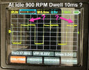
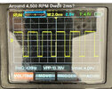
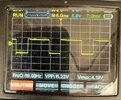
I managed to make a single D585 coil work without a computer and with a carbuetor by installing a hall sensor inside a Ford 302 Distributor. The hall sensor sends a 12V square wave directly to the Pin C of the coil. I have been doing some testing and have about an hour on the motor and so far so good. Idle is smooth and no issues even at 5,500 rpm. Looking the oscilloscope trace, I am seeing about 2ms dwell at 4,500 RPM. However, I see almost 10ms dwell at idle.

I know D585 likes to auto fire with too much dwell. What is the peak I am seeing between the 10ms dwell at Idle? Is the coil firing when it reaches maximum dwell at 5ms?

I am not seeing any iralic idle and very smooth.

Thank you,
 

Attachments

  • Pic1.jpg
    Pic1.jpg
    105.3 KB · Views: 29
  • Pic2.jpg
    Pic2.jpg
    104.9 KB · Views: 29
Last edited:
At 900 rpm, you can see that the voltage is reducing during the first half of each dwell period, and after the spike, the voltage is higher and steady.

What is happening is that the coil current is increasing during the first half of the dwell. That is normal, and that is what the dwell time is for, so that energy builds up in the coil.

The voltage reduction comes from the resistance in the supply wires, combined with the current taken by the coil.

At around 5 ms, something in the coil decides that the current is enough and turns it off, causing the spike and the spark. After that, there is no current taken by the coil so no voltage drop and the current is steady.

When that coil is used in a car, the engine management computer would almost certainly never let the dwell time get to 5 ms. The time-out within the coil pack is there in case there is a faulty computer or a short in the wires. and the current would just get really big, really quickly and blow fuses or burn out the coil or harness in a few seconds or less. That would be expensive in coils, or fuses if you are lucky, and would also be difficult to diagnose as there wouldn't be time to make measurements.

Older cars had a lot of resistance in the coil, so that the current stopped increasing once it had got to the correct value. However that was very inefficient with the large dwell times at tickover, and the coil was at its maximum current for a large proportion of the time. Also at high engine speed, with a mechanical contact breaker, the dwell time couldn't start immediately after the previous spark, and the compromises that allowed the coil to not overheat at tickover meant that there couldn't be as much current so the spark energy wasn't the best.
 
Hello,

Thanks for your reply.

What I don't understand is that I am probing the pulse signal line from hall sensor to the coil which is a sqaure wave. Why am I seeing a spike here ?

Also, if the coil was firing mid-dwell, would'nt I see it with my timing gun and timing mark? My idle is smooth, no misfire and timing is steady and not eratic.

Thanks
 
A 2.5ms dwell will you get >40kV driving the Gate of an IGBT on Pin C. The current to 64% depends on Tau= L / DCR
 
Last edited:
Hello,

Thanks for your reply.

What I don't understand is that I am probing the pulse signal line from hall sensor to the coil which is a sqaure wave. Why am I seeing a spike here ?

Also, if the coil was firing mid-dwell, would'nt I see it with my timing gun and timing mark? My idle is smooth, no misfire and timing is steady and not eratic.

Thanks
The coil current drops to zero very quickly and there are huge voltages in the spark. There will almost certainly be noise on any signal. The ground voltage will change and the size of the spike will depend a lot on where you connect the ground wire on the oscilloscope.

The point in time when the spark happens will be the earliest of:-
A) The pulse from the Hall sensor ending
B) 5 ms after the Hall pulse starts
At high engine speeds it will be A) and at low engine speeds it will be B).
The timing at low engine speeds will still be consistent. The 5 ms won't be jumping around. Also, the transition from A) to B) won't involve a jump in the timing.

If the timing is designed to come from the end of the Hall sensor pulse, you might have been lucky with the timing at low engine speeds, where the timing comes from the start of the Hall pulse, and the 5 ms timing from the coil. EIther of those times could be inconsistent, as there is no need for precise timing.

Also, the 5 ms cut out from the coil may be a cut out at a certain current, so the time would probably vary with temperature and voltage.
 
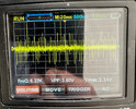
I put a scope on the 12V line to the coil and this is what I get at Idle and at 4500 RPM.
 

Attachments

  • WhatsApp Image 2024-09-04 at 2.08.21 PM (1).jpeg
    WhatsApp Image 2024-09-04 at 2.08.21 PM (1).jpeg
    97.3 KB · Views: 18
  • WhatsApp Image 2024-09-04 at 2.08.21 PM.jpeg
    WhatsApp Image 2024-09-04 at 2.08.21 PM.jpeg
    61.3 KB · Views: 19
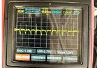
I think the old D585 coil was auto firings. I changed the coil out and installed D510C. The idle was much smoother with no spiking - see scope trace. The D510C did not autofire but lasted about 5 min before it got hot and died. Not sure if the 10ms wide dwell killed it or 12V pulse trains from the sensor. I am disappointed that this mod did not work. There is just no way getting around the 10ms wide dwell at idle.
 

Attachments

  • WhatsApp Image 2024-09-04 at 2.08.21 PM (2).jpeg
    WhatsApp Image 2024-09-04 at 2.08.21 PM (2).jpeg
    70 KB · Views: 19
  • WhatsApp Image 2024-09-04 at 2.08.21 PM (3).jpeg
    WhatsApp Image 2024-09-04 at 2.08.21 PM (3).jpeg
    96 KB · Views: 19
Looking at the voltage at idle, the voltage goes down initially during each pulse and then levels out. It is likely that is reflecting the current which is increasing for 3 - 5 ms and then being limited by the coil's resistance.

That is not how modern coils are supposed to run, so the heating will be far more than intended. It shows why other coils turn off after 5ms or when the current is too large.

Coils like that are not designed to be run directly from the Hall sensor. There is supposed to be a module in between to decide the timing.

It's not exactly new technology. I had a car with a knock sensor that used the processor to decide the timing, and it could adjust the timing separately for each cylinder. That was on a mass-produced car in 1984.
 

Latest threads

New Articles From Microcontroller Tips

Back
Top