I did a quick test, I wrote some code for a PIC which did the following:
set the frequency to 27MHz
wait 1mS
set the frequency to 0MHz
wait 10mS
repeat
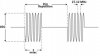
Loaded that into my AD9851 based signal source, and it worked quite well.
The phase at which the frequencies started and stopped was rather random, but it did generate 1mS bursts as required.
JimB