Continue to Site

Welcome to our site!

Electro Tech is an online community (with over 170,000 members) who enjoy talking about and building electronic circuits, projects and gadgets. To participate you need to register. Registration is free. Click here to register now.

  • Welcome to our site! Electro Tech is an online community (with over 170,000 members) who enjoy talking about and building electronic circuits, projects and gadgets. To participate you need to register. Registration is free. Click here to register now.

Garage Door opener- motor current control faulty

Status
Not open for further replies.

Cornboats

New Member
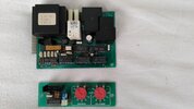
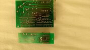
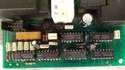
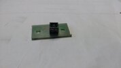
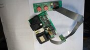
I have vintage Slavedor garage door opener that has stopped closing the door. If I disable the up/down current control to the motor it works fine. I attached the larger control board which is for everything and the smaller current control board.
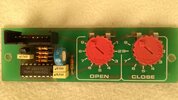
Normally the current control is set slightly above the maximum current normally used. If the door exceeds this it should stop and reverse when closing or just stop when opening. Can someone please explain how the current control board works so that I can try and repair or replace the defective parts.
I see my self as an interested novice willing to learn.
 

Attachments

  • IMG_20230118_100246455.jpg
    IMG_20230118_100246455.jpg
    1.8 MB · Views: 158
  • IMG_20230118_100254854.jpg
    IMG_20230118_100254854.jpg
    2 MB · Views: 165
  • IMG_20230118_100301717.jpg
    IMG_20230118_100301717.jpg
    1.6 MB · Views: 162
  • IMG_20230118_100315083.jpg
    IMG_20230118_100315083.jpg
    2 MB · Views: 160
The large electrolytic cap to upper right of relay, top view, is the top
of that cap bulging out ?

iu

iu


If so its failed, and possibly taken out some other components its connected
to.

Do you have a schematic ?


Regards, Dana.
 
The soldering on the current control board looks very poor particularly to the three low value resistors. (I suspect these could be current sense resistors.)

Les.
 
Electrolytic caps have been tested for esr and capacitance and are all ok.
The rear of the current setting board has been desoldered ready for parts pulling,probably why it look poor condition.
I haven't a schematic so if anyone can suggest a circuit I could build to replace the existing faulty current setting circuit I would welcome it.
 
Can you trace out the schematic of the current setting board ? With the bad soldering I could not follow all of the tracks. It is much easier to reverse engineer a board when you have it rather than working from pictures.

Les.
 
Les. I've had a go at doing a sketch of the torque adjustment circuit. Its not easy trying to follow each trace and draw it accurately but I've checked it several times and am pretty confident its accurate. I've posted it today along with 2 photos of an infrared tacho sensor that was fitted to the end of the motor shaft. This has a 3 wire flat cable which is part of the 8 way flat cable which connects directly into the board. The other 5 ways of the 8 way cable plug into the main board.
The TC 4538BP is numbered as per data sheet.
 

Attachments

  • Electronic Schematic.pdf
    790.9 KB · Views: 200
  • slavedor5.jpg
    slavedor5.jpg
    1.2 MB · Views: 149
  • slavedor6.jpg
    slavedor6.jpg
    1.4 MB · Views: 153
It looks like pin 4 or 5 (depending on which direction you have numbered the pins. ) on the connector is broken off. This connects to one of the force potentiometers so this is probably the cause of the problem. The broken pin may be stuck in the connector on the end of the cable.

Les.
 
Well done Les ? Your right of coarse it has broken off and I've been looking for a problem that wasn't there. I saw the pin was missing and just assumed, wrongly that it was a blank space on purpose.Even doing the schematic didn't make the old grey matter think.
Just goes to show 2 heads are better than 1. I've got to do a test after I've fitted everything back and fixed the broken pin issue but its got to be the odds on favourite cause.
 
Status
Not open for further replies.

Latest threads

New Articles From Microcontroller Tips

Back
Top