Continue to Site

Welcome to our site!

Electro Tech is an online community (with over 170,000 members) who enjoy talking about and building electronic circuits, projects and gadgets. To participate you need to register. Registration is free. Click here to register now.

  • Welcome to our site! Electro Tech is an online community (with over 170,000 members) who enjoy talking about and building electronic circuits, projects and gadgets. To participate you need to register. Registration is free. Click here to register now.

Gain difference going from LM358 to LM7322

Status
Not open for further replies.

ACharnley

Member
Hi all,

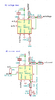
I have a differential mode op-amp being used to attenuate an AC signal down to a reasonable level for a ADC. It has a 1.5v offset. Op amp power is 12v, AC is no more than 30V.

Using the LM358 the gain calculation was spot on.

// resistor attuention 100k/2.4k = 41.6666666667

Using the LM7322, which should be a drop in replacement I'm seeing greater attenuation. At the ADC end a computation of ~11v equals about ~9v.

Am I missing something on the LM7322?
 

Attachments

  • Untitled.png
    Untitled.png
    10 KB · Views: 278
There's quite a difference in bias current. Don't know if this would explain it. LM358 takes just 45nA, LM7322 takes -1.2uA. Also compounded by one being + and the other being -.
 
I figure that could be it, when accentuating the signal as much as I am here it's going to play a greater part. It's not an aspect of op-amps I've had to look at before.
 
It's one of those things that isn't relevant, until it is.
 
I asked Texas Instruments.. They said....

"Input bias current should not be a factor because the inputs see the same the same impedance. The offset current would create a DC shift, not an AC attenuation. Have you tried more than one sample of LM7322?"

The chips are genuine, bought from RS so I'm not expecting a fault.
 
I wish I'd thought of that. Now I just feel foolish. I mean, of course it isn't! Was just the first thing to jump into my pretty little head... Nothing else is jumping in there.

Why don't you download models for LM358 and LM7322 and try simulating the circuit (actually if you use Tina-TI it might even come with them). These then are idealised versions of the chips and of course you can inspect the signals as closely as you like.

Also - 3 preset resistors seems a lot. Sure you can't manage with just RV3? You should look up supply splitting circuits - there are much better arrangements than your simple PD (and none of them aim for exactly 50%)
 
Do you get the same difference in performance with a DC signal?
 
Unable to try a DC signal, at least not easily.

The resistors could be overkill but was my attempt at getting less than 0.1% variance (assuming I picked those resistors up). I'm not sure what's better then the supply circuit I have. There's no feedback loop for heat change but I'm not expecting much heat change so didn't factor it. One reason for the change to LM7322 is 40mA output current (double that of LM358 which occasionally would have a tiny sag which triggered another part of the circuit not shown, a UVLO).
 
Link took a bit finding! It is worth the effort to read this, honestly :) (well it was for me; you might already know everything!)

Basically, with the 2 resistor PD the amp's PSRR goes to pot. Your PD is one amp removed from the real amp, but I think the principle's the same . Better to stabilise the voltage than to get it exactly 50% (there's an obvious disadvantage if the supply is a battery, however)

Thinking a bit more about your actual problem - I've seen full calculations for op-amps which include all the variables, not just R1 and R2 (ie, the non-ideal characteristics of the amp) - perhaps if you can track this information down and re-calculate for each type of amp you will get results which match your experiments.

Or perhaps you are seeing effects of an experimental setup (eg, breadboard) which only affects the LM7322? Power and ground impedance, perhaps?

Would it be viable to use an output transistor (or totem pole) to get the current boost, instead?

Your circuit reminds me of one I created a while ago - the unclean offspring of a diff amp and a summing amp is approximately what I called it. Worked very well but needed 3 matched resistors!

It's a shame none of the experts are chipping in here... Guys? Gals? Heloooooeee....
 
It's small factor surface-mount, all quite close with good grounding, multiple vias etc. The frequency (I forgot to state this) being measured is low, in the 10's of Hz.

I've got a backup in motion, the use of a second INA142 to measure the voltage. Under the hood it's using the same approach but the resistors are laser trimmed.
 

Attachments

  • Untitled.png
    Untitled.png
    19.2 KB · Views: 197
  • 11.png
    11.png
    41.3 KB · Views: 210
Status
Not open for further replies.

Latest threads

New Articles From Microcontroller Tips

Back
Top