Hello
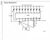
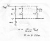
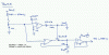
I have built a circuit described in the forum using the LM 3914 display driver and a resistor chain for a fuel gauge I am building. It uses a float switch to activate 10 reed switches to switch in resistors attached to the input as it moves down (10 in all).
I need some help in working out a way of latching the output signal till another switch is activated, it would remove the need for very careful reed positioning
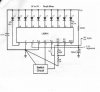
Can I feed the output of the display driver to a latch ic or ic`s and then to a uln2003s to drive the LED output. As the new signal from the reed is received it would need to the reset all the other outputs and wait for the next signal.
I am a little unclear of logic latches and if they can be used, output from the lm3914 would have to have a pull resistor take it to high and stop it to floating .
Any help would be appreciated its a long time since I did any electronics do they still do OC71 transistors!!
")
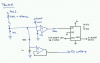
I have built a circuit described in the forum using the LM 3914 display driver and a resistor chain for a fuel gauge I am building. It uses a float switch to activate 10 reed switches to switch in resistors attached to the input as it moves down (10 in all).
I need some help in working out a way of latching the output signal till another switch is activated, it would remove the need for very careful reed positioning
Can I feed the output of the display driver to a latch ic or ic`s and then to a uln2003s to drive the LED output. As the new signal from the reed is received it would need to the reset all the other outputs and wait for the next signal.
I am a little unclear of logic latches and if they can be used, output from the lm3914 would have to have a pull resistor take it to high and stop it to floating .
Any help would be appreciated its a long time since I did any electronics do they still do OC71 transistors!!