jesusfreak
New Member
Hi,
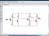
I need to get the Frequency of a guitar. The Amplitude must be 0V and 5V, i need to get the changes low to high with a Microcontroller to calculate the frequency.
My Problem is now, how to get the Guitar Frequency to Volotage, I used to do it with a bc547 Transistor, but the highest Voltage is about 2-3V, that is not enough.