Continue to Site

Welcome to our site!

Electro Tech is an online community (with over 170,000 members) who enjoy talking about and building electronic circuits, projects and gadgets. To participate you need to register. Registration is free. Click here to register now.

  • Welcome to our site! Electro Tech is an online community (with over 170,000 members) who enjoy talking about and building electronic circuits, projects and gadgets. To participate you need to register. Registration is free. Click here to register now.

Frequency to Voltage Converter LM2917 Circuit Setup

Status
Not open for further replies.

simply_me

New Member
Hello,

I'm attempting to convert a received signal frequency to voltage for a comparison/subtractor with the sent/original signal (I've a linear ramp oscillator). From the datasheet of the LM2917 f/v converter I know that Vout= Fin* Vcc*R1*C1.
If my original signal is about 4.2V (Vp-p), to which Vout should I design the circuit?
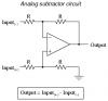
Ultimately, in the comparison stage, I need the voltage difference between the original signal and the one received (maybe I should have a subtractor?) in order to measure distance.

Thank you.
 
You question "If my original signal is about 4.2V (Vp-p), to which Vout should I design the circuit?" is not clear.

Is the "original signal" Fin?

What do you mean by "which Vout"? There's only one Vout.
 
Last edited:
Hi crutschow,
I'm building an ultrasonic rangefinder using a linear ramp. I'm sending a wave through the transmitter and also have a comparator on the receiver end to compare the received voltage with the transmitted voltage. Hence, the "original signal" is the wave straight from my linear ramp. Vout is the voltage out of the lm2917 that goes to the comparator, and I dont know to which voltage to set it (given the formula for it in my first comment). Also, I should mention that my Vp-p is 5.4v not 4.2v, I was too sleep deprived when I wrote it :)
 
What is the purpose of the linear ramp? Does it control a VCO? Please post a schematic or at least a block diagram.
 
The purpose of the linear ramp is to sweep frequency instead of relying on direct time measurement to find the distance. The linear ramp is fine, actually the transmitter side is complete, and I'm just trying to do the receiver side. I've attached the picture of the linear ramp waveform, if you are interested in the schematics of the linear ramp I'll be happy to attach them next.
 

Attachments

  • IMG_1713[1].JPG
    IMG_1713[1].JPG
    386.4 KB · Views: 528
I'm going to compare this wave with the wave received and then find the distance. That is why I need to know how to set my Vout in the lm2917 (the receiver end) to know how to compare the two.
 
Last edited:
Hi...

I think I see what you are trying to do,

You have a transmitter which uses a linear ramp to vary the ultrasonic transducers frequency.
You now are trying to create a reciever that will respond to the recived frequency with a voltage.
This voltage will be compared with the tranmitter linear ramp.

Okay so it sounds pretty simple... I would first need to know the frequency of the transmitted signal

Remember Vout= Fin* Vcc*R1*C1

So design Vout in such a way that it equals 5 Volts ( approximatly from your oscilloscope reading) at maximum Fin.

However when you compare the signals they will never be EXACT, you will need to factor in some kind of error margin

What will yo9u be using to compare the two signals? a microcontroller?
 
Thank you for your help.
The transmitted signal is centered at 40kHz +-500Hz.
I was thinking about Vcc=5V, Rin=27kOhm, C=1nF, Fin~40kHz, it gives exactly the same amplitude; I'm not sure that's the goal though.
I'll probably use a subtractor circuit along the lines of the attached image.
Also, off topic, would you recommend me to use and AGC or just amplify, filter, and then the subtractor and indicate the distance by a needle and tick marks (basically like an analog voltmeter, but I'm open to suggestions here too)? (also, given that I don't have much time to complete it)?
 

Attachments

  • 03336.png
    03336.png
    4.3 KB · Views: 721
Automatic Gain Control sounds complex :D

Help me understand something... the transmitter and reciver will be mounted next to each other and therefore the linear ramp signal will be availible on both sides?

Also how do you get distance by subtracting the two signals? I would think that distance was related to the phase differance between the two signals?

Also just a quick mistake, I belive Vcc needs to be more than 6V and also according to the datasheet Fin(MAX) = I2/(C1*Vcc) where I2 = 180uA
Your C1 value will not allow a 40kHz signal.

Also what do you mean by you frequency is centred at 40kHz? I thought the linear ramp sweeps the frequency from 0 -> max then 0->max ect with no "center" frequency? please elaborate

Regards,
StudentSA
 
You are the guy who tried to use a lousy old LM358 at 40kHz when it has trouble above 5kHz.
Then you uses a TL082 but had its input biased too low.
 
Status
Not open for further replies.

Latest threads

Back
Top