Huttojb1
Member
Hey.
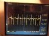
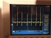
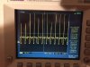
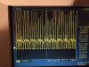
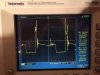
Please see attached, this is the signal that goes into my RPM Gauge of my kitcar. I believe it dirives from the coil.
Obviously I cannot put this directly into my PIC (Microchip Micro) and need to condition it to a 5V max signal.
Once I have conditioned the signal I could then use the capture function on the PIC to capture edges to work out frequency or I would like to convert this frequency in to a 0v to 5v signal. Either way is good. Would probably prefer to convert signal to a voltage as it makes it easier.
It seems like it goes from approx 5hz to around 160hz. I only screenshot 3 examples but the large one (87hz) was about half throttle.
If anyone could help I would be very appreciative because I wouldn't even know where to start.
The simpler the better because I would need to source all the components
Jason.
")
