Continue to Site

Welcome to our site!

Electro Tech is an online community (with over 170,000 members) who enjoy talking about and building electronic circuits, projects and gadgets. To participate you need to register. Registration is free. Click here to register now.

  • Welcome to our site! Electro Tech is an online community (with over 170,000 members) who enjoy talking about and building electronic circuits, projects and gadgets. To participate you need to register. Registration is free. Click here to register now.

Foldback Current Limiter Question

Status
Not open for further replies.

p5taylor

New Member
The circuit attached is of a foldback current limiter, what determines the 20mA at the low end of the current limiting, and is there a formula to calculate this.

Kind Regards

Paul
 

Attachments

  • Foldback.jpg
    Foldback.jpg
    41.3 KB · Views: 2,558
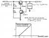
What is the emitter resistor of Q2 supposed to be?

I couldn't find either of the transistors in my LTSpice library, so I substituted ones that have similar specs, especially Hfe.

The circuit is very sensitive to the actual Hfe of Q1 (therefore, IMHO not a very good circuit).

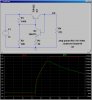
First figure shows the current limiting as a function of the load resistance, R4 with a WAG for R3. Red trace is the voltage output. Green trace is the current through R4. Note that for load resistance < 18.6Ω, the output current is ≈ constant at 20mA. For load resistance > 24Ω, the output current is inversely proportional to R4, so no current limiting there. Between those values, the fold-back is happening.

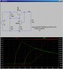
Second figure shows the effect of changing R3 from 2K to 3K to 4K (order: left to right). Note that R3 seems to effect the onset of current limiting, but doesn't effect the folded-back value of 20mA very much.

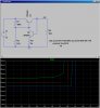
Third fig. shows the folded-back current as a function of Load resistance R4 while R2 is varied from 50K to 80K in steps of 10K (order: Green, red, lt. blue and dk. blue, respectively). The f.b. current is a function of how much base current flows out of Q1.

This should give you something to work with.
 

Attachments

  • DF74a.jpg
    DF74a.jpg
    218.9 KB · Views: 687
  • DF74b.jpg
    DF74b.jpg
    241.8 KB · Views: 574
  • DF74c.jpg
    DF74c.jpg
    173.8 KB · Views: 637
Yes, that circuit depends upon the Hfe of Q1 to determine the current limit and is thus a very poor design. It's current limit will depend upon the particular transistor you happen to have, since Hfe varies widely from unit to unit.
 
Here are some examples.
 
you could get a similar effect using a constant current source as the limiter. the output voltage would begin decreasing when the current limit is reached, but the current will remain constant at the set-current of the CS. this is sometimes confused with foldback limiting, but it's only the voltage which folds. the required power dissipation for the current source is higher than a true foldback limiter.
 
unclejed613 that sounds interesting, i never thought of it that way to be honest so this would be a voltage foldback circuit? so in a current foldback the current decreases but do the voltage remain the same?

Kind Regards
 
Crustchow provided a good selection of web pages which show the many ways foldback current limiting can be implemented.

But as one of the app notes there warns, foldback limiting has some caveats:

" Linear foldback can have problems tripping current limit during start-up and returning to full load after a fault condition. These problems tend to lock up the Regulator in current limited state"

Therefore, if you implement a current foldback scheme, don't make it very aggressive...in other words, that the foldback is no less than 40 or 50% of the full rated current.
 
Therefore, if you implement a current foldback scheme, don't make it very aggressive...in other words, that the foldback is no less than 40 or 50% of the full rated current.

I agree, this overhead rated current percentage is essential.

A poorly designed foldback circuit based on the rated load current can/will cause problems.

E
 
commercial vendors like Power-1 don't usually have the foldback percentage at an aggressive level either, usually something like 70-80% of the trip current (20-30% reduction). looking at a commercial supply schematic (one that uses standard off-the shelf components) would be very useful

some schematics and other information is here:
https://www.djerickson.com/p1hack/
 
Last edited:
Because of the latchup problems, some people prefer "hiccup" current limiting schemes.
Yes, I used a hiccup current limit scheme at the input of a SMPS to avoid dragging down the input power source in case of a fault (fuses and circuit breakers were forbidden). That allowed for very low dissipation in the current limit circuit thus requiring no heat sink.
 
Status
Not open for further replies.

Latest threads

New Articles From Microcontroller Tips

Back
Top