mstechca
New Member
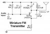
Lets take a simple FM transmitter.
What components should I deal with and how should I change them? I want to optimize it for distance, but I also want to hear the transmitted tone on the receiver as well. I don't care if the tone changes frequency, but I still want to hear it when the transmitter and receiver are far away.
What components should I deal with and how should I change them? I want to optimize it for distance, but I also want to hear the transmitted tone on the receiver as well. I don't care if the tone changes frequency, but I still want to hear it when the transmitter and receiver are far away.