Continue to Site

Welcome to our site!

Electro Tech is an online community (with over 170,000 members) who enjoy talking about and building electronic circuits, projects and gadgets. To participate you need to register. Registration is free. Click here to register now.

  • Welcome to our site! Electro Tech is an online community (with over 170,000 members) who enjoy talking about and building electronic circuits, projects and gadgets. To participate you need to register. Registration is free. Click here to register now.

FM transmitter whats a matta' with it (again)

Status
Not open for further replies.

zachtheterrible

Active Member
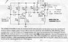
I've built this transmitter here once and it worked pretty good, even though I think that I was hearing harmonics over the radio. Well, I built this same transmitter again, but w/ some small changes:

Where C4 is, I put another capacitor in series w/ it. Actually, I took an ic socket and cut it so that I could solder two sockets into the circuit and then be able to put different capacitors in, therefore being able to have a huge range of frequencies.

I also made L1 smaller. It is supposed to be 1/4 an inch w/ 6 to 8 turns, but I made it 1/8 an inch w/ the same amount of turns.

The circuit does not work. I made a very simple RF field detector that works great, and it picks up nothing. Last time that i built this circuit, it didn't work, and come to find out later, all that was wrong with it was I burnt C3 while soldering. I was very careful with that capacitor this time; I put a heat sink on it.

Anyways, I made a metronome that produces a series of clicks, or whines, depending on the value of capacitor in it. Is this a reliable way to test the higher value capacitors in this circuit?

The two changes that I made to the circuit, they wouldn't make the circuit stop working, would they? Since I made the inductor smaller, this would boost the frequency, but how much? I put in a higher value capacitor for C4 (100 pf), so hopefully that would lower the frequency enough so as not to go above the transistor's highest frequency rating.

Lastly, is there a way to test the transistors without pulling them out of the circuit?
 

Attachments

  • fmtrans_114.jpg
    fmtrans_114.jpg
    265.4 KB · Views: 552
zachtheterrible said:
Where C4 is, I put another capacitor in series w/ it. Actually, I took an ic socket and cut it so that I could solder two sockets into the circuit and then be able to put different capacitors in, therefore being able to have a huge range of frequencies.

At VHF layout is critical, you shouldn't use sockets, and wires on components should be kept short. Putting capacitors in series makes the resultant capcitance smaller - was that what you wanted?.
 
Ahh, how stupid of me :? , I just realized that what i meant to say was that i put the capacitor in PARALLEL w/ C4. With my putting the socket in, it might mess things up a little, but wouldn't I still get a signal on my RF detector anyways?
 
with the RF detector i'm guessing it has a frequency range on it, mine does atleast, so it is possible the changes you made put the transmitter frequency higher or lower than the detectors working range.

With L1, changing the length of the coil would change the inductance even if you used the same number of turns.

L = (r(squared) * n(squared) ) / ( 9r + 10b )
____________________________________
L = inductance in uH.
r = radius of the coil (in inches).
n = number of turns in the coil squared and;
b = the length of the coil in inches.

I would figure out the inductance for the new coil, since you said it could be 6 to 8 turns i don't think that would be all that critical. But you can figure out the LC circuit again just to give a general idea if mathmatically the transmitter should work with the changes you made.
 
The RF field detector is actually something that I built, and consists of nothing but a germanium diode, a resistor, an antenna, and two alligator clips. You hook up the two clips to a multimeter, and if there is indeed an rf field, then you will see voltage on the multimeter.

I ran the math earlier on my inductor, and i forget what it said, but I remember that it showed that the inductor being 1/8" wouldn't change the frequency A LOT. I was just wondering if someone could tell me about how much affect the change from a 1/4" to a 1/8" inductor would have. I'm not totally sure that I did the math right.
 
I have this terrible feeling that my question kind of got forgotten about . . . The question is, is using a metronome a good way to test the higher value capacitors in this circuit? The first posting has a little bit more detail. Tanx :lol:
 
PLEASE!! No one's anwering my question: Is using a metronome a good way to test the higher value capacitors in this circuit!?!?

While i'm @ it, i've got another question: I measured the the base and emitter voltage to see if the circuit is indeed oscillating, and I got 7.5 for the base, and 8.1 for the emitter. The battery i'm using is a 9 volt battery that is puttin' out 8.5 volts (old battery). Is this a correct reading for this circuit? Thanx (if you answer my question) :lol:
 
A metronome is a poor way to test any capacitor. It will only give a indication of value and not much more.

According to your voltage readings, I would say you have a bad transistor. Emitter voltage should be less than 1 volt.

Gary
 
Thanx!! The way that i measure caps is to take two of the same value, and compare the sound . . . if the cap was defective, wouldn't it not work, or make a different sound?
 
First make oscillator work (disconnect one end of the C2 capacitor
for now). Once the oscillator is running, you should be able to find
spot on your receiver that is prefectly silent. If you touch the transmitter
with a pen or similar, you should hear scratchy noise from the receiver.

Mentioned voltages are waaay out of whack.
Are you sure transistor is functional and connected correctly?
Sounds like you swapped base with either collector or emitter...
 
Well . . . I replaced the transistor, and when I tested it, I found out that it was indeed fuctional, but I replaced it anyway. The emitter and collector are not wrong. My tester tells me which lead is which. I know for a fact that C2, C3, and C4 are perfectly fine. My wiring is also fine foresure. As I mentioned earlier, I have an RF detector, and it is picking up nothing, so I know foresure that my oscillator is definately not working. Any other ideas????
 
Status
Not open for further replies.

Latest threads

New Articles From Microcontroller Tips

Back
Top