Continue to Site

Welcome to our site!

Electro Tech is an online community (with over 170,000 members) who enjoy talking about and building electronic circuits, projects and gadgets. To participate you need to register. Registration is free. Click here to register now.

  • Welcome to our site! Electro Tech is an online community (with over 170,000 members) who enjoy talking about and building electronic circuits, projects and gadgets. To participate you need to register. Registration is free. Click here to register now.

FM transmitter [Oscillator Help]

Status
Not open for further replies.

chicaman

New Member
**broken link removed**

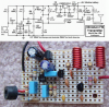
I am building a 2 transistor FM transmitter.

I have some problem in transmitting the FM signal and I believe the problem lies on the Inductor.

I am using 2 x 27pF capacitor and an inductor 0.255 uH and using this equation, i am suppose to get 84Mhz from this

**broken link removed**

but when i tune my radio to 98.30MHz I am able to listen but there are lots of noise. Now the oscillation doesnt work anymore.

So I replaced the 2 x 27pF capacitor with 2 x 47uF capacitor and the transmitter frequency changed to 118.x MHz and the voice is clear. I noticed that from the spectrum analyzer, I need to increase the capacitor capacity to bring the frequency lower so it can be in range of 88MHz and 108MHz.

I plan on buying extra capacitor for trial and error purpose but its totally different from the calculated Frequency of Oscillation.

Or is it my air coil inductor problem?? I am having a hard time to get a good air coil inductor. Any guide for me to coil a better inductor?

Please help me and replies are highly appreciated. Pardon my bad English. Thanks in advance
 
I have built a couple of simple FM transmitters like yours. I can tell you, right up front, that they are plagued by instability and parasitics. Just moving the antenna around can change the operating frequency. Just waving your hand near the circuit can change the operating frequency. A change in the room temperature, or just letting it self heat can move the operating frequency.

More to your question, the bias on the transistor from the modulator affects the calculated operating frequency, which is not included in your formula.

It's a fine circuit for experimenting with, but not very practical. In a well designed, stable circuit, the oscillator would be better isolated from the modulator and would be crystal controlled.

Don't fret, the circuit is most likely working as well as that design can. A little tip I can offer: You can tweak the operating frequency by mechanically moving the turns on the coil, moving a couple of turns farther apart, or closer together.
 
Last edited:
Yea I tried by tweaking the inductor turn by pulling it by giving it more space in between each turn and compressing it, it does give some changes.

I tried changing with 6 different Transistor and I do see changes in the operating frequency from spectrum analyzer. Well from what I see now, they only changes I can make now is increasing the capacitor capacity. If it doesn't work well then I might have to coil a new inductor :D
 
Last edited:
Stability is still going to be a problem over the long term.
 
There are a number of faults with the circuit. The first one being the direct connection between the first and second transistors.

The other this is the 47u. It should be about 22n to tighten up the circuit for the RF. <snip> We have a 9v version that transmits more than 600m and is extremely stable. It will pick up a pin dropping on the floor and the result from an FM radio is so clear, you don't know if it is a radio or someone speaking in the next room. It's not just the inductance of the coil but the "Q" of the coil.
 
Last edited by a moderator:
There are a number of faults with the circuit. The first one being the direct connection between the first and second transistors.

Could you tell us why, in your opinion, why the direct connection is a fault.?

The other this is the 47u. It should be about 22n to tighten up the circuit for the RF..
Could you explain exactly what this statement means.?

Look forward to your reply and please dont tell me its 'magical'.

BTW: I would suggest you dont use the Forum as an advertisment for your site. IMHO, it amounts to spam.
 
Last edited:
The direct coupling of the two stages is to be avoided as the small amount of noise on the collector of the first transistor is being directly coupled to the oscillator transistor. The oscillator stage should be self-biased and the base should be held rigid as it is a common-base stage.

The 22n on the power rails is effective at 100MHz and it improves the output of the RF stage enormously. An electrolytic has a high impedance at 100MHz.
 
The direct coupling of the two stages is to be avoided as the small amount of noise on the collector of the first transistor is being directly coupled to the oscillator transistor. The oscillator stage should be self-biased and the base should be held rigid as it is a common-base stage.

If that was correct, which it is not, then how would the audio modulate the RF carrier.???
BTW: its a common emitter stage, not common base.

The 22n on the power rails is effective at 100MHz and it improves the output of the RF stage enormously. An electrolytic has a high impedance at 100MHz.

What you should said, is to ADD a 22nF to the power rail decoupling, leaving the 47uF in place.!

Why do you insist on giving misleading advice to posters.?
 
I think the value of the 2.2pf feedback capacitor is too low. Try 4.7pF to 10pF.

The 2.2nF capacitor from the base of the RF oscillator to the positive supply is a low impedance path to ground (if the supply bypass capacitor is a 0.022uF ceramic).
The impedance of the 2.2nF capacitor at 100MHz is only 0.7 ohms.

My FM transmitter project has an RF amplifier to isolate the antenna from the oscillator and to increase the range.
It has a low-dropout voltage regulator so that the frequency does not change as the battery voltage runs down and to keep the mic preamp properly biased.
It has pre-emphasis like FM radio stations have so its sound from an FM radio is perfect.
 

Attachments

  • FM transmitter pic + schem.PNG
    FM transmitter pic + schem.PNG
    195.9 KB · Views: 397
The second transistor is a common-base arrangement.
You can see the base is held rigid at 100MHz by the inclusion of the 2n2 on the base to positive.

The 47u is not needed in this circuit but a 22n across the power rails will improve the output of the oscillator considerably when the battery gets weaker (when the impedance of the battery increases).
 
Last edited:
47uF takes care of filtering the voltage of the Audio amplifier activity, pehaps and it is needed I feel.
 
The audio is being injected into the RF stage. The 10k on the mic is too low and you will get "motorboating" from the front end.
 
Last edited:
Most electret mics operate at 0.5mA then a 10k resistor from 9V is perfect.
I agree that the 10k resistor that feeds the mic should be decoupled from the 9V with a 1k resistor is series from 9V then a 47uF capacitor to ground. Then there will be no motorboating.
 
The second transistor is a common-base arrangement.
You can see the base is held rigid at 100MHz by the inclusion of the 2n2 on the base to positive.
How is the base held 'rigid' by the 2n2.???

The 47u is not needed in this circuit but a 22n across the power rails will improve the output of the oscillator considerably when the battery gets weaker (when the impedance of the battery increases)

The 47uF is required to decouple the +V power rail, as is also the 22nF

.

I suggest you get some formal training on electronics.
 
The base of the 100MHz oscillator is held rigid by the 2n2 as it has a very low impedance at 100MHz.
I have designed over 25 RF transmitter circuits like the one shown (except all of mine have a self biasing oscillator stage) and sold over 100,000 kits.
An electrolytic is not needed on the supply rail as the audio is being injected into the RF stage and the current taken by the microphone and audio stage is very small in a well designed circuit. It is an unnecessary component.
However a 22n on the supply rail will improve the stability and increase the output of the RF stage as this stage is drawing heavy peaks of current.

The reason why the two stages should not be DC coupled is as follows: The oscillator stage needs to be self-biasing for stability. If is connected to the collector of the previous stage, this self-biasing is negated.

Most of that reply is just nonsense.!
 
Status
Not open for further replies.

Latest threads

New Articles From Microcontroller Tips

Back
Top