John Sorensen
New Member
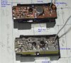
For all the discussions about FM transmitters lately, and SMT construction techniques, here's a picture that shows the technique I've been blathering about. The transmitter that is copper colored has a solid ground plane. The other one doesn't because it's actually cut into the ground plane of a scrap PCB.
j.
j.