Continue to Site

Welcome to our site!

Electro Tech is an online community (with over 170,000 members) who enjoy talking about and building electronic circuits, projects and gadgets. To participate you need to register. Registration is free. Click here to register now.

  • Welcome to our site! Electro Tech is an online community (with over 170,000 members) who enjoy talking about and building electronic circuits, projects and gadgets. To participate you need to register. Registration is free. Click here to register now.

flip-flop +/- on motor for fwd/rev control

Status
Not open for further replies.

garrettp

New Member
have an old spot light for my boat. The joystick was broken off and I purchased a newer one since I have no idea of the make of the spot light.

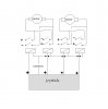
So, the spot as two motors up/down left/right. The motors only have two leads. The new joystick has positive out for either of the 4 positions and a single ground.

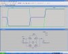
How can I wire it so the + and the - flip on the motor depending on forward reverse?

I hope I explained this well enough. Below is a pic of the boat I am restoring :)

**broken link removed**

Thanks in advance.
Garrett
 
I'm thinking something along the lines of four 12volt DPST (double pole single throw) mechanical relays, two assigned to each motor. Each relay coil will be assigned one of your joystick positive outputs and all return to common on the joystick. As each motor gets TWO relays, the two sets of contacts on each relay will independanty switch your battery (+) and (-) terminals...except each motors relay pair will be wired opposite in polarity.

I'll quickly draw something up.
 
OK here is a quick rendering using MS/PAINT

the polarity of each relay contact is marked plus or neg and would be wired directly to the battery, for space I didn't draw the battery or those leads.

Your browser may shrink the image and "erase" some of the lines representing conductors. Click on the image to zoom in if that is the case. Broken lines represent no connection made (crossing points).

The relay coils are the box with diagonal lines, and each has TWO normally open switch contacts above it.

You may understand my symbols already but using the paint program it helps to describe my poor art :)
 

Attachments

  • joystick.jpg
    joystick.jpg
    33.5 KB · Views: 559
Last edited:
The only concern you might have with this circuit is if one relay ever failed closed, wich would be rare, you might have a short circuit, so you might want to fuse protect both the positive and negative battery leads in that case.

There might be a better way to do this, but this is what popped into my head.
 
Here is another idea. V2 and V3 represent right and left positive leads ( or up and down leads ) The 100 ohm resistor is your motor. As the right or left voltage goes positive, the current in the motor reverses. (Blue trace)
 

Attachments

  • HBridge.JPG
    HBridge.JPG
    120.3 KB · Views: 392
Good solution BrownOut.

The primary benefit to the mechanical relays, I suppose, is ease of troubleshooting, repair, and finding replacement parts. If he gets the modular type relays that plug into a base with screw terminals for each contact point and coil, he could build this in a project box without etching a board or using a soldering iron...just a drill, mounting screws, and perhaps some grommets for the cables and wires.

I hope to hear some feedback.
 
That's a real nice boat, BTW. I think who's ever idea works should get a free ride :)

PS: looks like the link to the picture got hosed.
 
Last edited:
I will host the boat picture on another site. The boat should be a fun project.

As for my electrical skills, I am extremely good at SMD work and re-work. I am very good at trouble shooting a circuit. As for building a circuit, forget it. And with that, I am so glad you guys are here.

As for what I need, Kerf's (short for ke5frf) idea would of course be the most simple. However, I would like something compact since it will have to go behind the dash (which is aka: the head). So, BrownOut, could you help me out a little more :) I take it these are surface mount chips? what part numbers and do I have to go to digikey or will radioslack have them?

I do wish I was more circuitly inclined to match my other work ability :(

As for a ride on the boat, h#ll yeah. I got this for a party boat. It has no floor or stringers so I have a lot of work to do. The hull, motor and drive are in excellent shape. I will have to take some pics of it in my garage too. LOL 15# of sh!t in a 5# bag.

Thanks so much for your help so far.
garrettP
 
I have a boat that's missing the deck and stringers. I began to restore it years ago, but never finished. I also have a sailboat and ski boat. I love boats and the lake. Trying to figure out a way to live there and just go boating every day.

Do you know what the current requirements are of your motor? We just need to find FET's that are speced to handle your current and voltage. The 100 ohm resistor in the diagram was just a wild-ass guess (WAG) I'll have to look at some specs if you can determine the current. We can find something; it isn't all that complicated.
 
Last edited:
I will take pictures of one of the motors tomorrow. I would assume though that the current draw is extremely low (once you see them I think you will agree lol). As a test I held the assy from moving to see how strong the motors where... Not very.

As for boats, I live on the bay of Green Bay in Oconto. I started with a jetski and then got a 14' jetboat. The jetboat has lights and I take it across the bay to Door county and return after dark. My neighbor owns a marine service and that is where I got the old 24' Thompson (made just north of me in Peshtigo in 1976). With this boat I plan to hit the water on Friday afternoon and not return until Sunday night ;) My neighbor also gave me a 17' Crestliner that only needs a bow repair. No idea what I am going to do with that yet.

I just moved the pic to the folder with pics of my jetboat Index of /pics/jetboat

What kind of boat are you restoring? If, in return for helping me, I can help you in anyway to finish your project, please let me know.
 
Look at some of these products. They include all the devices you need to build the circuit. The are surface mount, so they will be a challenge to mount. However, Digikey sells small proto boards that you can mount them to, and that brings all the leads out to pins.

**broken link removed**
 
Last edited:
Good luck on your project!

And if you have any roadblocks, the relay idea is there for you if you need it. FYI depending on the power rating of your motor you might find some pretty small relays to do the trick
 
I checked out digi-key and had no idea what I would need. I know they are very helpful, but I stopped at Radio Slack and purchased to small DPDT relays. Below is a diagram of how I have them wired. I also purchased a small circuit board and with a little cutting I will be able to fit the PCB inside the joystick housing :).

Thanks a ton for your help and idea's. This place rocks.

**broken link removed**
 
Status
Not open for further replies.

Latest threads

New Articles From Microcontroller Tips

Back
Top