Continue to Site

Welcome to our site!

Electro Tech is an online community (with over 170,000 members) who enjoy talking about and building electronic circuits, projects and gadgets. To participate you need to register. Registration is free. Click here to register now.

  • Welcome to our site! Electro Tech is an online community (with over 170,000 members) who enjoy talking about and building electronic circuits, projects and gadgets. To participate you need to register. Registration is free. Click here to register now.

Finding the right relay

Status
Not open for further replies.

dranobob

New Member
As I've said in a previous post, its been 10 years since I was playing on a bread board. So I remember a lot of the concepts, but its all a hazy memory.
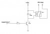
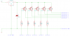
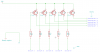
I'm trying to find a relay, I assume just a relay. I have a series of switches that when pressed, close a circuit to ground. The controller I'm using is looking for 5v inputs. I need a relay (I have 5 inputs in fact, so i'm assuming 5 relays, or 1 ic would be even better). That when it detects ground on one of the 5 switches, that it sends 5v (the controller provides the 5v on a common) to the corresponding input on the controller. I'm not sure the mA, but its got to be tiny. The controller is nothing more than a control board for a keyboard, so the 5v input is from when a key is pressed it closes the circuit for that key, sending 5v.
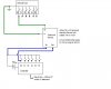
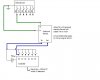
 
Hi,

Think you are saying you have a controller chip with 5 input switches that when pressed, the controller turns on a corresponding relay .. ??

The relay choice is determined by two key things - the drive current available from your controller chip, which if too small will need a drive transistor to activate a relay, and also what type of votlage /current will the relay contacts be taking?

Does your circuit really need a relay - ? using a 5v circuit with relays does give some voltage problems - if you are just controlling 5v then a transistor switch or chip might work just as well... but cannot say more on the info provided
 
sorry, I'll try to elaborate.

I have switch that has 5 buttons on it. With 5 leads and 1 ground. One lead to each button...when a button is pressed it closes the loop of that lead to ground. I can not change this setup, because it is part of another piece of equipment, so the action of connecting each lead to ground is done internally.

I also have a separate controller (it actually connects to a PC). That has 5 inputs (actually many more, but I'm only using 5). When 5v dc is applied to an input, the controller sends a signal to the software in the computer.

I need a relay or device (that runs on 12v dc) that when it is connected to ground, it closes the loop (when the loop is closed it has to be able to handle 5v and a tiny amount of milli-amps). So essentially a switch that is watching to be grounded, when it is, it closes the switch, allowing the 5v to pass through.
 
Last edited:
I didn't understand where the 12V or relay comes in?

The existing switches are already providing a ground when actuated. Right?

The inputs to the PC expect either 0V (ground) or 5V for a 0 and 1, respectively. Right?

You have a 5V supply the negative terminal of which is grounded. Right?

Connect a 1k pullup resistor from each switch wire to +5V. Also connect the switch to the PC input. The PC will see 0 if the switch is closed; 1 on all the open switches. You may have to redefine what a 0 and 1 means in the software. It is easier to rewrite the software than to wire in 5 relays.

If you cannot invert the meaning of the signals in software, then use a CMOS HEX inverter chip to invert the five signals.
 
Last edited:
Hi,

As MikeMI mentions, your description is a little difficult - however it might be better if you can do a small diagram so we can see what your really mean.

Have just done a relay section from your description thats suitable for one of the many cheap little PCB DIL type relays.
 

Attachments

  • relay.jpg
    relay.jpg
    8.6 KB · Views: 147
that diagram looks like what I'm trying to do, but just to be sure, here is my attempt at diagramming "what I'm trying to do."

Forgive me for its crudeness, I am at work and only have paint to draw with.

Obviously this only shows for one button and one input. I can't change the arrangement of either the Remote or Controller. Consider them black boxes.
This will be running in a car, so if the device requires a voltage to operate, I have 12v to power it.

I was hoping to find a "device" like I show, but I don't mind putting together components (diodes, resistors, transistors, etc) to build such a device myself, but I am so out of practice I would need values and even better model numbers.

I know I'm being a pain, but I really appreciate the help
 

Attachments

  • diagram.JPG
    diagram.JPG
    26.5 KB · Views: 154
Last edited:
What is the voltage between S1 and S0 when an input switch is open? (edit: I guess we can define this, right?)

Can the Ground (S1) be tied to the ground on the PC?
 
Last edited:
But that diagram you have drawn will send 0V when the switch is pressed, because Vin is connected to the negative side of the battery. I thought you wanted to send 5V when the switch is pressed?
 
1y5zdzjy, it looks to me that your diagram is exactly what I'm trying to do, except I could use the 5v off of the controller instead of using a 7805 to downgrade the 12v (essentially ignoring my statement of having 12v as an external power supply).

To make sure I'm understanding. The Transistor wont allow the 5v to pass to controller, unless there is closed circuit to ground (via the switch). Am I understanding that right?
 
...check this one out

You didn't answer the question if the ground symbol on your drawing is tied to the ground on the PC interface?
 
fantastic, that is it. I appreciate the help. What kind/model number transistors should I order (or a single IC with 5 or more transistors), and whats the best place to order in small quantities.
 
Last edited:
If you can tie gnd together on the switch and the controller this will do what you want:...

It might work most of the time :D

Good engineering practice requires five additional resistors from each PNP base to +5V to guarantee that the PNPs will turn off. Additionally, your circuit makes a big assumption that there is a pull-down resistor on each of the inputs to the PC interface, so that the input signal is at a defined "LOW" when the PNP transistor is off. If that pull-down resistor is not there, you would have to add five more resistors, so we are up to 15 resistors, 5 transistors.

I would use five channels (out of six) of a CD4069 CMOS hex inverter. Put a 4.7K pullup resistor (other end tied to +5V) on each switch/each inverter input. Power the inverter package on +5V. Wire the five inverter outputs to the five inputs on your PC interface. This requires five resistors and one hex inverter.
 
Last edited:
Good engineering practice requires five additional resistors from each PNP base to +5V to guarantee that the PNPs will turn off.
That is incorrect.

Additionally, your circuit makes a big assumption that there is a pull-down resistor on each of the inputs to the PC interface, so that the input signal is at a defined "LOW" when the PNP transistor is off.
Yes it does make that assumption, based on what dranobob said "When 5v dc is applied to an input, the controller sends a signal to the software in the computer."

2N3906 (TO92) or FMMT591 (SOT-23) will both work for the transistors.

Mouser Electronics - Electronic Component Distributor is a good place to order parts in the US.
 
considering I can't even get totals over $2 I'm going to build both setups ;) Try em both and see which I like best. Even if they both work perfectly....I used to love to build circuits and been way too long....will be fun
 
question can you order small boards to solder the components to? I remember using the bread boards back in college, but I'm looking something about 2" square.
 
Status
Not open for further replies.

Latest threads

New Articles From Microcontroller Tips

Back
Top