Continue to Site

Welcome to our site!

Electro Tech is an online community (with over 170,000 members) who enjoy talking about and building electronic circuits, projects and gadgets. To participate you need to register. Registration is free. Click here to register now.

  • Welcome to our site! Electro Tech is an online community (with over 170,000 members) who enjoy talking about and building electronic circuits, projects and gadgets. To participate you need to register. Registration is free. Click here to register now.

Filter White Noise Generator Output < 20Hz

Status
Not open for further replies.

pnielsen

Member
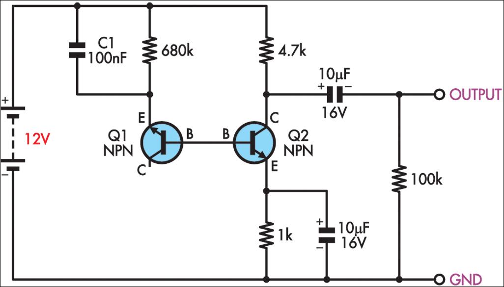
I have built this white noise generator using BC547's. The output reaches about 10Vpp.

http://www.next.gr/uploads/69/simple-white-noise-generator-circuit-diagram-3.jpg

I would now like to add a filter so that the generator only outputs frequencies below about 30Hz.

Can someone please advise me how this may best be accomplished? I tried a few passive RC combinations, but they kill the output. If an op amp is required, I would prefer single 12V supply. I have LM358's and LM386's on hand. Thank you for any suggestions.
 
Before we filter out high frequencies, this circuit is not making low frequency noise.
Look at Q2. There is a RC on the emitter. That RC causes the Q2 amplifier to not pass frequencies below 16hz. This circuit was built for "audio" and starts to not function below 20hz. I do not know this circuit well but I know that increasing 10uF to 100uF will help the low frequencies. (so what frequencies do you want?) Also what simple filter did you try?
simple-white-noise-generator-circuit-diagram-3.jpg
 
Upping the 10u on the o/p to 100u might also be a good idea, esp if the load impedance is on the low side.
It looks like they are using the Be junction of Q1 in a similar manner you'd use a zener to generate noise, the 680k provides Dc bias, C1 will also have an effect on noise frequency, if you get the thing on a audio spectrum analyser you might want to fiddle about with C1 as well to get an even response.
As for filtering low freq's you'll need a sharp filter, something like a 4th order, there are sites that will calc active filters for you, if your into that kinda thing Ltspice simulator was made for this, you might need a special part for Q1 though.
 
I suggest moving C1 to between the emitter and ground!

Two reasons:
As shown the signal path includes the battery, with no decoupling to bypass it, which is not good practice.

More important, when turned on, the caps charge at possibly unlimited current via the two transistor B-E junctions and that could easily damage one or both transistors.

Changing to larger capacitors makes damage far more likely with the circuit arrangement as shown.
 
Linear Technologies has some simple to use, high order filters. Check their website, use the parametric selector tools.
They are quite pricey though.

Otherwise is cascaded opamp filters. There are several online calculators. But you'll require several capacitor and resistor values.
 
there are quite a few low pass filters that can be used. active filters using transistors or op amps can give you a filtered output without reducing the ourput voltage. a simple one would be a second order filter using a transistor, or you could build a state-variable filter with a quad op amp. the state-variable filter has the added advantage of having a high pass and a band pass output in addition to the low pass output.
 
Given the 20Hz lower cutoff of the uploaded circuit, I now understand why the output disappeared when I added a single stage 30Hz op amp filter. I will also try the suggestions regarding component changes, including the decoupling cap and sharp filter. Thank you for pointing me in the right direction.
 
Status
Not open for further replies.

Latest threads

New Articles From Microcontroller Tips

Back
Top