Continue to Site

Welcome to our site!

Electro Tech is an online community (with over 170,000 members) who enjoy talking about and building electronic circuits, projects and gadgets. To participate you need to register. Registration is free. Click here to register now.

  • Welcome to our site! Electro Tech is an online community (with over 170,000 members) who enjoy talking about and building electronic circuits, projects and gadgets. To participate you need to register. Registration is free. Click here to register now.

FETs in ESD generative tube?

Status
Not open for further replies.

Flyback

Well-Known Member
Hi,
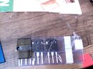
These FETs are 600V (SiHG186N60). The tube is clear plastic , from Farnell.
I thought all ESD safe plastics were tinted red or pink?

SiHG186N60
SiHG186N60 datasheet
 

Attachments

  • FETs in non ESD tube.jpg
    FETs in non ESD tube.jpg
    90.4 KB · Views: 164
ICs come in clear tunes all the time.

The tube in the picture is extremely likely the tube the manufacturer ships the fets in. They probably have a clue about what's safe.
 
Thanks, i think generally , due to the total outsourcing of electronics to the Far East from UK, we dont have a clue about anything to do with electronics now.....i was once at an enormous company in UK , who were bringing a 100W LED driver to market, with a BCM PFC follwed by 100W BCM flyback.....the 100W flyback had for a primary snubber, nothing more than a series UF diode into an SMB TVS!! This kind of cluelessness pervades in the British electronics sector.

This product also had a "Pilot" 1W flyback in it...which used the same snubber as the 100W flyback......for the 1W flyback, it was acceptable.

At another huge co in uk....they were bringing to prototype a 600W buckboost.....current source......all there engineers had failed to fix it....but it had no output overvoltage clamp, so if ever started on no load, it woudl simply kill itself with overvoltage....also, it had a 1milliohm sense res which was not at all kelvin connected....so it was more like 2 milliohms due to PCB trace res!.....nobody realised this, after 6 months of it not being able to be brought up...this is what happens when you outseource your electronics to the Far East.

...Nobody has a clue.

Then i can tell you about the isolated 20W flyback....which wasnt actually isolated as theyd put a ground plane from pri to sec ground......and even after it being pointed out, they didnt realise till a week of being told it was wrong........there softy woudl have got well electrocuted had they have made it.

Then i can tell you about the 150W (peak) flyback which had NO primary clamp whatsoever!!...and no primary current sense whatsoever......(the txfmr was well in saturation at the actual peak current threshold level that had been set)
 
Last edited:
Thanks, i think generally , due to the total outsourcing of electronics to the Far East from UK, we dont have a clue about anything to do with electronics now.....i was once at an enormous company in UK , who were bringing a 100W LED driver to market, with a BCM PFC follwed by 100W BCM flyback.....the 100W flyback had for a primary snubber, nothing more than a series UF diode into an SMB TVS!! This kind of cluelessness pervades in the British electronics sector.

This product also had a "Pilot" 1W flyback in it...which used the same snubber as the 100W flyback......for the 1W flyback, it was acceptable.

At another huge co in uk....they were bringing to prototype a 600W buckboost.....current source......all there engineers had failed to fix it....but it had no output overvoltage clamp, so if ever started on no load, it woudl simply kill itself with overvoltage....also, it had a 1milliohm sense res which was not at all kelvin connected....so it was more like 2 milliohms due to PCB trace res!.....nobody realised this, after 6 months of it not being able to be brought up...this is what happens when you outseource your electronics to the Far East.

...Nobody has a clue.

Then i can tell you about the isolated 20W flyback....which wasnt actually isolated as theyd put a ground plane from pri to sec ground......and even after it being pointed out, they didnt realise till a week of being told it was wrong........there softy woudl have got well electrocuted had they have made it.

Then i can tell you about the 150W (peak) flyback which had NO primary clamp whatsoever!!...and no primary current sense whatsoever......(the txfmr was well in saturation at the actual peak current threshold level that had been set)

For us newbies on SMPS sure sounds like you could be the author of a good "Safe SMPS Design" ap note.


Regards, Dana.
 
due to the total outsourcing of electronics to the Far East from UK, we dont have a clue about anything to do with electronics now

I have to disagree with that. There are many members here from the UK, members that know what they're doing and talking about. The only one that stands out that fits your description seems to be you!
 
Status
Not open for further replies.

Latest threads

New Articles From Microcontroller Tips

Back
Top