Continue to Site

Welcome to our site!

Electro Tech is an online community (with over 170,000 members) who enjoy talking about and building electronic circuits, projects and gadgets. To participate you need to register. Registration is free. Click here to register now.

  • Welcome to our site! Electro Tech is an online community (with over 170,000 members) who enjoy talking about and building electronic circuits, projects and gadgets. To participate you need to register. Registration is free. Click here to register now.

feedback question

Status
Not open for further replies.

Kit0302

New Member
hey guys.

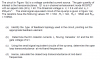
the question is attached.

It should be a series-series feedback topology.

but I don't know how to do the DC analysis in part(b), can someone help me with that?

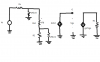
And to determine the open loop transconductance at mid-band frequencies, I have drawn a small signal equivalent circuit (open loop), can someone just check whether it is correct?

Thanks a lot.
 

Attachments

  • question.png
    question.png
    76.6 KB · Views: 264
  • figure.png
    figure.png
    28.6 KB · Views: 270
  • small signal.png
    small signal.png
    16 KB · Views: 275
Hello again,

I can help but it will have to be tomorrow, sorry.
 
Hello again,


Got a little busy today dealing with some computer related problems. Anyway...

Lets start with the small signal model. Do you understand all the circuit symbols and how to go about solving this circuit from left to right?
 
Hello again,


Got a little busy today dealing with some computer related problems. Anyway...

Lets start with the small signal model. Do you understand all the circuit symbols and how to go about solving this circuit from left to right?


Yes! I learned those before.

but I don't know how to do the part(b) in the question, which is find out the Io and Gate voltage.

And also I draw a small signal model to determine the open loop transconductance at mid-band frequencies, please see the third attached file. Is it correct?
 
Hello again,


Your small signal model "AVid" is drawn like a dependent current source when really it should be a dependent voltage source. You'll have to change that.
 
Last edited:
Hello again,


Your small signal model "AVid" is drawn like a dependent current source when really it should be a dependent voltage source. You'll have to change that.

oooops..

yes, that should be a dependent voltage source. I didn't draw it correctly.
Is there any problem with this small signal model? If I want to use it to calculate the open loop transconductance at mid-band frequencies?


And also, how to solve part(b)? find the Io and gate voltage?
 
Hello again,

It looks ok now, do you know what 'gm' is equal to?
 
Hello again,

Ok, well if you knew what gm was you would use that to calculate Io, but if you dont then you have to look up the model for the FET to find out what Id is with gate voltage. I can check around if i have a model like this but it's been a long time since i needed that so im not sure if i can find it or not. It will relate V^2 to the drain current something like I=A*(Vg-Vt)^2, where A=1/250ua. It's been quite a while though so that may not be the exact expression.

See if this helps:
https://en.wikipedia.org/wiki/JFET#Mathematical_model

or:
https://en.wikipedia.org/wiki/MOSFET


Sorry i cant be a little more specific with this right now, but i'm also dealing with some browser hijacking that im trying to get rid of. I think i'll ask around about that here too.
 
Last edited:
Status
Not open for further replies.

Latest threads

New Articles From Microcontroller Tips

Back
Top