Continue to Site

Welcome to our site!

Electro Tech is an online community (with over 170,000 members) who enjoy talking about and building electronic circuits, projects and gadgets. To participate you need to register. Registration is free. Click here to register now.

  • Welcome to our site! Electro Tech is an online community (with over 170,000 members) who enjoy talking about and building electronic circuits, projects and gadgets. To participate you need to register. Registration is free. Click here to register now.

Fan Control System

Status
Not open for further replies.

DeDogs

New Member
Working with 230V 50Hz AC House electrics.

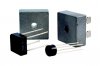
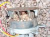
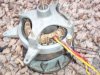
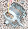
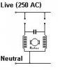
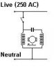
Got a 230V 10A DC motor I’m connecting to a fan for an air conditioning unit in my house. For the conversion from AC to DC I’m using a bridge rectifier and need some form of control for the speed of the motor so I can minimise noise. The way I see it if I connect a potentiometer to the DC power in to the motor I can august the speed of the motor? :?: :?: :?:

I’m sure there are some other components I need to connect? Anyone make a quick wiring diagram of the bridge rectifier and stuff, my dad and I would be well pleased
:)
 

Attachments

  • 19088i0.jpg
    19088i0.jpg
    18.3 KB · Views: 916
Yes the quick and dirty way of controlling the speed of a DC motor is by connecting a pot in series with it, but you need to know how much current the motor is drawing. That might be written on the motor housing as FLA. You need this to determine the wattage of the pot you will need.

An easier approach is to use power resistors and a selector switch. This will give you selectable speed control, witch is more common for fan controls.
 
Is the rest of the air conditioning system prepared to adapt to the various speeds? Evaporator air flow as well as condenser air flow can be changed but only within limits. Too little air flow on the evaporator and you make ice, you don't fully evaporate refrigerant, among other things. Too little air flow on the condenser and you can't cool the hot gas from the compressor.
 
Hi DeDog,

Yes, you can control smaller motors with a variable resistor,
its normal to put this in line with the field winding.

On a larger motor such as you describe, over 2kw, i don't think
using a variable resistor would be practical.

I assume the motor has the field winding in parallel with the
armature winding, yes ... ?

Could you describe the motor, such as does it have brushes?
does it have a centrifugal switch?
Does it have to start under load, or can load be applied once
its running?

Any numbers or model indication or makers name on it?

I was wondering if you could use a dimmer-switch on the field
dunno, i'll have to have a think ...

Is it expected to be running continuously or will it be
switching on and off with temperature?

And as Stevez says, the air-con won't work properly if
the motor speed drops very far, if you want to control air
con by reducing motor speed, running too slow will give other
problems, it may be ok for reducing by a small amount.

Regards, John :)
 
Sorry for not answering sooner but been a bit busy round the house.

There are two motor's i have both off washing machines, one has a lablewith some information the other has nothing. The one without any details does not have any brushes orcannot see any and the wires to power it go stright into the windings. The other motor is from italy and is made by SOLE Type 20584 024, AC-EL, CL. B/F, 220/240V 50Hz 300/14000 Rpm.

50Hz? that sounds like a AC motor to me? i just went and tested it with a 15Amp fuse (last one blew) and reved up then shut it self off think i just blew one of the windings :roll: plus all the lights in the house went dull when i tested it. I'm thinking we'll forget about that motor :lol:

And were left with the one without any writing on it and wires going striaght into the windings.

To clear up about the air conditioning - there is not its just a fan attached to this motor behind some (alot) or radiators to blowhot air into my dads home built swimming pool. No coolingwill take place.

The way i've designed it, a room thermostat controls a zone valve and motor's to blow hot air out of ducting in the floor. when the temperature is reacher the thermostat turns the live wire off and fans stop no more hot waterallowed into the radiators.

Not sure if i will have to use a relay for the fan motors inclueding the one im trying to get working now there are 2 other tiny motors about 1 Amp each.

The point about a dimmer switch seems great, but would you put it before the bridge rectifier to lower the voltage or would youput it after in which case will it work in a DC circuit?

Cheers everyone for replying :)
 

Attachments

  • Image2.jpg
    Image2.jpg
    8.7 KB · Views: 991
  • Image3.jpg
    Image3.jpg
    45.4 KB · Views: 793
  • Image4.jpg
    Image4.jpg
    42.6 KB · Views: 760
Motor im using is image4, image5 and image6 i.e the DC one without all the wires comming off it
 

Attachments

  • Image5.jpg
    Image5.jpg
    42 KB · Views: 759
  • Image6.jpg
    Image6.jpg
    60.7 KB · Views: 692
Hi DeDogs,

Images 4, 5, & 6 look like a shaded pole AC motor to me.

If they are, you should have two identical windings
with a common wire.

Check that with a meter and note the common wire.

It will probably be a bit like the diag below,
one switch for one way, other for the other way.

You will need a cap to run it, hard to say what size
over ten mfds, maybe twenty, depends on windings.

John :)
 

Attachments

  • Live.jpg
    Live.jpg
    4.2 KB · Views: 836
Hi DeDog,

Yes, you will need the cap to start the motor running,
but it can be run on one winding if you spin it manually
(not recommended)

It will take more current when its not turning.

With the cap in circuit, both windings contribute to
running the motor, the cap provides a phase shift to
give direction to the motor.

The cap has to be 'Non Polarised'
The cap must not be marked red or pos on any terminal.
The cap must not be an electrolytic.

Motor capacitors are typically roughly a quarter the
size of the motor, maybe a fifth these days.

I would guess at maybe 12 MFDs for that motor.
Sorry, i don't know how to tell the proper value easily.
Maybe someone else could give an opinion?

Somewhere between 10 and 20 should be ok.

That diag is for running either way,
here is one for only one direction.

Best of luck with it, John :)
 

Attachments

  • Motor.jpg
    Motor.jpg
    4.2 KB · Views: 684
A shaded pole AC motor

It will probably be a bit like the diag below,
one switch for one way, other for the other way.

Before i wrote this post i pluged the motor into the mains using just a blue wire and a black one, but the motor just made a humming noise. Do i need a capacitor for the motor to run at all?

You will need a cap to run it, hard to say what size
over ten mfds, maybe twenty, depends on windings.

I dont have much knowlage of motors so do i have to count all the windings or can i just get a big capacitor that will handle alot of windings?

How do i wire it in also just in seiries with the live cable?

(rang up maplins told them i dont need the bridge rectifier any more) :)
 
Status
Not open for further replies.

Latest threads

New Articles From Microcontroller Tips

Back
Top