Continue to Site

Welcome to our site!

Electro Tech is an online community (with over 170,000 members) who enjoy talking about and building electronic circuits, projects and gadgets. To participate you need to register. Registration is free. Click here to register now.

  • Welcome to our site! Electro Tech is an online community (with over 170,000 members) who enjoy talking about and building electronic circuits, projects and gadgets. To participate you need to register. Registration is free. Click here to register now.

Eliminate a relay, make it semiconductors...

Status
Not open for further replies.
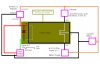
Is there some sort of a way to eliminate the area of this circuit that is
boxed by the lime green (the relay and if necessary the diode). I'm guessing
I need a couple transistors which will switch the negative signals, one that
gets triggered by a positive signal (and it's circuit will draw up to an amp,
but ideally I would like it to handle two amps), and the other triggered by a
negative signal (and it's circuit will draw up to about 300ma, but I would
like maybe 500ma, or even an amp just to make sure). Any ideas what
devices/transistors/circuitry I could do this with (see attachment for circuit).
 

Attachments

  • eliminate a relay.JPG
    eliminate a relay.JPG
    62.8 KB · Views: 364
You do realize, one is being switched with a positive 5v
and the other is being grounded...I'm sure this will work with
one but how is the other going to conduct (if they're the
same transistor, doesn't that mean they'll both come on
when the line in is +<pnp> or -<npn>) ??? It's only one
line in, at gnd or +5v. Will I need to invert the signal for
one of them (I'm using some 74ls86's in the circuit
anyways)?
I like the looks of the tip41c, lots of current.
Also, in your circuit, I am going to need to sever the
connection from the battery to the common, and use
only the charger to the tip41c on the right in the drawing. Correct?
 
Last edited:
You do realize, one is being switched with a positive 5v
and the other is being grounded...I'm sure this will work with
one but how is the other going to conduct (if they're the
same transistor, doesn't that mean they'll both come on
when the line in is +<pnp> or -<npn>) ??? It's only one
line in, at gnd or +5v. Will I need to invert the signal for
one of them (I'm using some 74ls86's in the circuit
anyways)?

I isolated the voltmeter and your charging system. The two transistors allow only the paths from Vcc-(Charger or Voltmeter)-GND when it is switched on. Just imagine those transistors as a simple open switch, with the current from base to GND will turn 'em on.
 
I want the meter connected 5% of the time, and
the charger connected 95% of the time. The Astable
timer is only for an automated meter sampling of the
battery. The charger will always be connected to the
battery (float charger) <except during sampling>
unless I turn IT off, but I will still want the meter to
continue sampling.
 
Last edited:
maybe this will explain it better...

BUT...I think the inverter needs to be for the other transistor !
 

Attachments

  • BARGRAPH.JPG
    BARGRAPH.JPG
    61.1 KB · Views: 218
Last edited:
This gets more interesting..
See the datasheet for this part: L293 push pull driver
This chip is used to invert current directions, for motors mainly (clockwise and anti-clockwise)
Incorporate this chip (very cheap) into your design. See it serves your purpose.
I'd love to see your progress. Good luck.

cheers.
 
Especially since I am already using an XOR, I could just use
one of them (of the 8 in two dips), to invert the astable output
in order to drive one of the tip241's, right?

The other XORs are inverting a bar/dot driver to change the
volt meter's astable timer's resistor, so the frequency of it's
output changes (to flash a LED at a different rate depending on
the battery's status <full/partial/crucial/etc.>.

You don't see any problem with having the 74LS86 driving one
of the tip241's, do you? I would like to leave all of the voltmeter
circuitry off until the sampling timer comes on, but to invert the
signal I'll have to leave one of the XORs powered, unless of course,
you know of a TTL device with just one or two XORs in it...
 
I'm not a fan of inverters.... The TIP42c, by the way, have very low saturation current, so yes, you can even put a 1KΩ between the output of the XOR or your 74LS86 to the base. This will also stabilise the circuit since there might be some oscillations. Also, a 1N4148 diode for data transmission is good to add with series with the resistor.

Build the circuit. I think it should work.
 
Last edited:
I am using 1N914/4148s on the output of the 74LS86, after the resistor
being tied to the 2nd. astable timer (allowing only the selected resistor to tie
to the Vcc) for the bar/dot driver (voltmeter). You say I should have the 1K
between my 1st. (95/5) astable output and the bases of both tips, right?

Do you have any idea how to make an XOR using GP transistors?

Also, might you know, I suppose it's OK to tie the bar/dot driver's outputs
together (through a signal diode), but do you think it might wreak havoc if I
tie them w/o diodes? I'm only going to have to use about half of the driver
(off/slow/faster/fastest/continous lighting of the single monitor LED).
 
You say I should have the 1K between my 1st. (95/5) astable output and the bases of both tips, right?

yes. This stabilizes the circuitry, and saves energy.

Do you have any idea how to make an XOR using GP transistors?

It's pointless to do so. There are commercial models for such special function chips.

Also, might you know, I suppose it's OK to tie the bar/dot driver's outputs together (through a signal diode), but do you think it might wreak havoc if I tie them w/o diodes?

I think it is better to use separate diodes for both inputs for the base. It might create inverse current if you don't use diodes. Your voltmeter might not get correct readings. This is the case when I'm using microcontrollers.
I'm only going to have to use about half of the driver (off/slow/faster/fastest/continous lighting of the single monitor LED).

You mean PWM drive? whatever it is, a diode into the base is a good practice. However, it may be sufficient to not put one for function. But if you want a stable circuit, it is advisable.
 
I mean, if I tie the outputs of the bar/dot driver, should I use diodes (this
is after the transistors). I would like to make an XOR w/ a few GP transistors, in
order to conserve space as opposed to a whole dip (I am using one 74LS86 which
has 4 of them, for different oscillation levels of the single LED, having the bar/dot
select the resisitor for that LED's astable frequency, and would like to keep the 4
levels of flash rate, but then I would need a whole 'nother 74LS86 and only be
using one gate in it <to invert one of the tips>).
The circuit...one astable varies it's output, connecting the battery to the
charger circuit (one of the tips). When that variable duty astable inverts (5%)
of the time, I invert it's signal to drive the voltmeter (disconnecting the battery
from the charger and connecting the battery to the voltmeter). The voltmeter
circuit is a bar/dot driver, outputting a negative signal (but I need a positive),
so the 74LS86 is inverting the signal, connecting different resistors to the 2nd.
astable, so the single LED from it flashes at a different rate depending on how
high up the bar/dot driver (in dot mode) is (according to battery voltage). The
resistors get a diode before the timer, but I want to tie multiple outputs to the
same resistors (instead of 10 sets of resistors and diodes).
 

Attachments

  • circuit.JPG
    circuit.JPG
    28.1 KB · Views: 180
I would like to make an XOR w/ a few GP transistors, in order to conserve space as opposed to a whole dip (I am using one 74LS86 which has 4 of them, for different oscillation levels of the single LED, having the bar/dot select the resisitor for that LED's astable frequency, and would like to keep the 4 levels of flash rate, but then I would need a whole 'nother 74LS86 and only be using one gate in it <to invert one of the tips>).

Yes, I understand what you want to do. But building your own gates is not space-saving AT ALL. There are TTL (transistor-transistor logic) schematics, but it is just to guide you to understand how gates work. These circuits are fabricated optimally, while building these gates from scratch is not wise. You'd be better off with the DIPs.

Here's the bulky design of an XOR:
https://upload.wikimedia.org/wikipe...XOR_from_NAND.svg/300px-XOR_from_NAND.svg.png

Each NAND is https://t1.gstatic.com/images?q=tbn...1/TTL_NAND_003.svg/618px-TTL_NAND_003.svg.png

See?

The voltmeter circuit is a bar/dot driver, outputting a negative signal (but I need a positive), so the 74LS86 is inverting the signal, connecting different resistors to the 2nd. astable, so the single LED from it flashes at a different rate depending on how high up the bar/dot driver (in dot mode) is (according to battery voltage). The resistors get a diode before the timer, but I want to tie multiple outputs to the same resistors (instead of 10 sets of resistors and diodes).

Why are you using 74LS86 to invert signals? Here's an inverter IC for you:
https://www.electro-tech-online.com/custompdfs/2009/12/sn74ls04rev5.pdf

As for the resistors, I'd put in each input. It may be tedious, but it stabilizes your circuit.
 
As for the resistors, I'd put in each input. It may be tedious, but it stabilizes your circuit.

Do you mean, the diodes? Between the bar/dot driver and my tying the outputs together?
 
oh.. diodes? I see not much harm if you ignore the diodes.. but if your IC have reverse current effects you might need to include them. You can try first. If there is no problem, carry on without diodes. I doubt it can damage your IC if you don't have the diodes.
 
Status
Not open for further replies.

Latest threads

New Articles From Microcontroller Tips

Back
Top