Different set op........
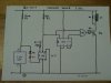
In order to not show anything from the outside of the case (at least on my grandfather clock), I think I might try a setup like this:
**broken link removed**
Because of the lesser mechanical leverage I would pulse it on each swing.
Hope the drawing is clear enough to illustrate what I mean, I newer took drafting.
RODALCO said:Mark,
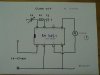
I used the old relay E shaped former for the magnetic field.
(This was an ex streetlight contactor from the POCO i work for, which was open circuit)
These relays or contactors have two E slapes which close when ac is put on the coil.
I only use one E shape of the latter.
The other E shape is used for the other clock coil.
The original coil was stripped of all it's wire and than cut in half to make the coil fit on exactly one half E former.
I glued an other end piece on the half coil to make it as a bobbin.
Then used my handwinder built from Meccano and put on about 300 turns of thin wire ( haven't got a gauge ) but wire i have a big reel off.
I'm making another coil for another experiment and will take photo's as i progress.
Kind regards
Raymond
In order to not show anything from the outside of the case (at least on my grandfather clock), I think I might try a setup like this:
**broken link removed**
Because of the lesser mechanical leverage I would pulse it on each swing.
Hope the drawing is clear enough to illustrate what I mean, I newer took drafting.