Continue to Site

Welcome to our site!

Electro Tech is an online community (with over 170,000 members) who enjoy talking about and building electronic circuits, projects and gadgets. To participate you need to register. Registration is free. Click here to register now.

  • Welcome to our site! Electro Tech is an online community (with over 170,000 members) who enjoy talking about and building electronic circuits, projects and gadgets. To participate you need to register. Registration is free. Click here to register now.

Electronic timer accurate to the 1000ths of a sec

Status
Not open for further replies.

Electrodawg

New Member
Hi I am new to the forum and was wondering if there would be someone that would be willing to help me build an electronic timer that is accurate to 1000 ths of a sec? I am very handy know a little about electronics but not a lot, have soldered a lot and built simple electronics before and can read basic schematics, would mostly need the help designing the over all circuit.

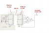
This is what I have in mind:


I plan on using a temperature compensated crystal oscillator using a frequency of 1mhz, and dividing it down to 100hz. I would use a 555 timer circuit for the clock generator, but unfortunately they are too inaccurate for this purpose. The crystal oscillator is accurate to +/-1ppm, so out of 1 million pulses in a second, it might miss one pulse. I can live with that kind of accuracy. The clock generator signal will not start until after the start button is pushed. Once the timer starts, it will be directed into a Counter/Display driver, which uses a 4 digit 7 segment LED display. Four digits will get me 0.000-9.999 seconds. The laser module will be set at the finish line, opposite an enclosed photodetector circuit. When the beam is broken, the counter will stop, leaving the finished time displayed on the main box.

So that quote makes me sound like I really understand electronics but I found that on the web when looking for schematics for electronic times. Someone else is wanting to build the same thing I would like to build but unfortunately that post was very old and did not go into any details at all.

I there is anyone who you like to help out a guy and maybe get me started? I would really appreciate it!

Sincerely,

darren
 
Why are you trying to build something that can be easily purchased?
 
For millisecond resolution I think you might just be able to use a 555 timer with it's timing resistors and capacitors. You probably want to use a CMOS 555t timer though because 1ms ia relatively long time period. You don't need a crystal, but if you want to use then you don't need a 555 timer and you could use a much lower frequency crystal. In particular a 32.768kHz crystal becaue those are made for real time clocks because 2^15 cycles of those crystals is one second which is convenient for use with digital counters.

Why are you trying to build something that can be easily purchased?
Is it a laser beam triggered timer easy to buy? Doesn't seem to me like it would be.
 
Last edited:
Crutschow

I was am not aware of a timer that is sold that can be started with a switch and then stops when a laser beam is broken. If you know who sells such a device could you point me in the right direction?

As well I kind of wanted to build it myself thought it might be a fun project. From the little research I have done it does not sound like a electronic timer is that hard of a project but I have just started looking into it so much to learn.

THX
 
First is build a circuit that outputs a string of 1ms tick or pulse every 1ms. Possibly with signals to stop and start the ticker also (though this may not be needed depending on whether the counter can be made to just ignore incoming clock pulses with another signal).

You can always add on laser beam triggers and counter displays later.

You could also maybe bust open a stop watch and wire a laser trigger to the stop button.

I am curious what you are using this for though, because when one wants to measure something with 1ms accuracy, one also usually needs to be able to stop AND START the timer with the same accuracy. So far you only have a way to stop the timer.
 
Last edited:
Buy one of those plastic sports stopwatches from a sports shop etc, and hack into it. It should be easy enough to attach your own method of starting/stopping it (instead of the buttons it has).
 
I was am not aware of a timer that is sold that can be started with a switch and then stops when a laser beam is broken. If you know who sells such a device could you point me in the right direction?

You need a pinewood derby timer!!!!

Thay start with a switch at the starting gate and stop at the finish line when the car bracks the beam. Many of them record the times on a computer.

As well I kind of wanted to build it myself thought it might be a fun project. From the little research I have done it does not sound like a electronic timer is that hard of a project but I have just started looking into it so much to learn.

Thare are DIY vershoins on the internet.
Andy
 
Last edited:
There are no shortage of turn key timer solutions out there. You can likely hack a digital stop watch or look at some of the many Pinewood Derby timer solutions along the lines of similar to this one.

However, if you choose the DIY method to build your own there are a few things (terms) you need to get familiar with as they apply to counters and timers.

Hi I am new to the forum and was wondering if there would be someone that would be willing to help me build an electronic timer that is accurate to 1000 ths of a sec?

That is sort of an open statement. What you seem to want is a display that can resolve down to three places to the right of the decimal. That is more a matter of resolution than accuracy. Resolution being along the lines of the ability to read an instrument or of the instrument to be read. It says nothing of the accuracy or uncertainty. The fact that the timer in this case can display 3 places to the right of the decimal point simply means it can display out to .001 second but nothing about how accurate the numbers will be.

The quote you used from another forum or that you found online:

I plan on using a temperature compensated crystal oscillator using a frequency of 1mhz, and dividing it down to 100hz. I would use a 555 timer circuit for the clock generator, but unfortunately they are too inaccurate for this purpose. The crystal oscillator is accurate to +/-1ppm, so out of 1 million pulses in a second, it might miss one pulse. I can live with that kind of accuracy. The clock generator signal will not start until after the start button is pushed. Once the timer starts, it will be directed into a Counter/Display driver, which uses a 4 digit 7 segment LED display. Four digits will get me 0.000-9.999 seconds. The laser module will be set at the finish line, opposite an enclosed photodetector circuit. When the beam is broken, the counter will stop, leaving the finished time displayed on the main box.

Note the mention of PPM (Parts Per Million) which defines the accuracy or uncertainty of the oscillator. Actually it could be a drift rate from a nominal of 1.000000 MHz but we won't worry about that. One PPM works out to be ± .00010% or at 1.000000 MHz ± 1 Hz which is pretty good for most applications. If I resolve out to 3 places that 1 Hz won' t amount to anything. If I resolve out six places .000000 it would only amount to ± 1 count in the last place.

Now if I were to build a counter to have a resolution of .001 second I would not even think about considering the 555 in an astable mode as a clock. Here is why. If we read the data sheet for the 555 timer IC which can be found here. We will see that using it in an astable mode as a clock oscillator has an allowable error of 2.25% or expressed in PPM about 22,000 PPM. The allowable drift rate is 150 PPM per degree C of temperature change. Actually pretty lousy specifications if you want to do somewhat accurate measurements of time resolving out to .001 second. Another option was using a 32.768kHz crystal oscillator and using binary division to get the frequency down. This will not work well or easy either. The reason is if we begin to divide 32,768 Hz down using divide by 2 functions we get 16,384, 8,192, 4,096, 2,048, 1,024, 512, 256, 128, 64, 32, 16, 8, 4, 2, and last but not least 1. The 1 being a very nice 1 second time base but not what I want. I want a 1 KHz ( .001 second time base). One second is nice for my watch but not what I want for my timer.

So what to do? I buy one of these little oscillators for literally less than $3.00 USD. Then I use some divide by ten counters like the CD4017 to divide my 1 MHz clock down 1,000,000, 100,000, 10,000, 1,000 and I have my pretty accurate 1 KHz (.001 second) clock. Using one of these has some nice features, I get pretty good accuracy but I also get a nice gate thrown in. I can apply a simple signal to Pin 1 to open or close my clock gate. Open the gate and my 1 KHz pulses are counted, close the gate and they stop. The open and close become the Start / Stop for my counter.

Overall, hack a stopwatch! :)

Ron
 
basically you need a 1kHz signal with some accuracy and a counter with 3 decimals. (0.000)
you can use a crystal oscillator with 4060 IC (devide by 16384 counter + oscillator) and a 4026 (counter + display driver IC)
if you can find a 16.384 MHz crystal then its a matter of assembling it.
or even you can use 3.2768 MHz crystal as shown on the attached diagram for example. see the datasheet of 4026 too.
 

Attachments

  • time base-2.JPG
    time base-2.JPG
    36.9 KB · Views: 699
Four digits 0.000-9.999 seconds

How wide is the cross line? 1m max?

How many targets and counters? How do you overcome targets blocking each other? What does the target look like? (size)

DId you want each lane with a 4 digit counter> how many lanes?
Display over lane? or all combined?
 
Can you answer me post #12
 
Please say what it is you want to do, assuming of course your post is legit.

John
 
Status
Not open for further replies.

Latest threads

Back
Top