Electro Tech is an online community (with over 170,000 members) who enjoy talking about and building electronic circuits, projects and gadgets. To participate you need to register. Registration is free. Click here to register now.
Welcome to our site! Electro Tech is an online community (with over 170,000 members) who enjoy talking about and building electronic circuits, projects and gadgets. To participate you need to register. Registration is free. Click here to register now.
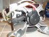
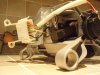
Hard to say exactly. But it looks like you have a reversable DC or univeral type motor. two of the wires run the field coils(the stationalry ones on the outer part)Two of them will go to the bruches. and it also looks like it may have some sort of speed sensor on the end.
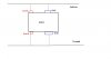
Try putting the field and brush wires in series. That should spin it up. but if its a DC only it may not run very well on AC that way. To reverse it just reverse the connections one either the field or the armature.
Can you give us a model of the wash machine? Perhaps some one here has actual schematica or hands onexperiance with it. then they can tell you exactly what you have and how to hook it up.
Looks like a "universal motor" to me, too. The white and black appear to be the brushes, yellow and brown are probably the field. That thing on the back with the two red wires is probably a magnetic speed transducer, it has a coil and a magnet on the shaft, gives you a sine wave with a frequency proportional to the speed.
That would work but I think it will be cheaper and more efficient just to buy a 12V motor.
Are you sure it's parallel wound? Most motors like this tend to be series wound.
You can power it directly from DC, in fact it will be more efficient run from DC than. It won't be very fast off 12V though. If you want to power it from DC, use a lower voltage than 230V, due to the fact that the winding inductance won't limit the current. As a guess, running it from 48VDC will probably give you similar performance to the mains.
I'm afraid i'm struggling to understand how these motors work. Googling universal motor i see that it is designed to run off both AC and DC. There seems to be 2 ways to control speed, pwm or phase shifting, why cant i just vary the voltage with a potentiometer?
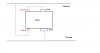
i have no idea if its parallel or series wound. I'm not exactly sure what this means, is this when brushes and field are inline, so i would then connect my motor as in my new sketch below?
How can i tell if its series wound or parallel wound?
I would go with the connection that you have in the second post. And like they said try it at a lower voltage first.
As far as AC or DC series wound universal motors generealy dont have any change in efficiency from one to the other. AC does tend to give some a hum or growl when under load. But at the same input voltage there is no real measurable difference.
Does a power drill or any other device with a universal motor have any speed or power difference between AC or DC input?
In a mass production level like a wash machine they may have went with a simple phase control circuit to varry the speed.
But I am just guessing.
CAREFUL WITH THE SERIES WOUND MOTOR - they tend to speed up and blow themselves to hell if you run them unloaded.
My experience is they are usually parallel wound. Could it be they are series for 220V and parallel for 110V?
Hero999, do you have a formula for relating the DC equivalent voltage of a universal motor to the AC rating? I looked around, couldn't find one, be a handy thing to know.
As far as AC or DC series wound universal motors generealy dont have any change in efficiency from one to the other. AC does tend to give some a hum or growl when under load. But at the same input voltage there is no real measurable difference.
When run from DC there are less losses because the current doesn't reverse there will be no hysteresis losses in the field coils and the eddy loss will also be lower.
I found that out for my self by removing the fan from a series wound vacuum cleaner motor. Luckily the motor wasn't too badly damaged, just one of the brushes suffered a bit of wear.
My experience is they are usually parallel wound. Could it be they are series for 220V and parallel for 110V?
That may be true.
It probably also depends on the appliance, I'd imagine electric drills to be parallel as they're often operated unloaded. I assumed a washing machine would be series because it's always loaded but I'm obviously wrong.
Hero999, do you have a formula for relating the DC equivalent voltage of a universal motor to the AC rating? I looked around, couldn't find one, be a handy thing to know.
No, I just discovered I could power a 230V vacuum cleaner motor well off 48V, actually it was probably closer to 56V and it might not have been running at full power.
I'll have a play around if I ever manage to get hold of a load of SLAs to connect up in series. I was at work when I did this last.
This kind of thing could be handy for example if you want to use power tools in a damp environment, to eliminate the dangers associated with mains, you could stick DC connectors on them and run them from batteries or a DC PSU in a safe location.
what kind of current should i expect with 24v DC? I plan to try running this motor using my bench power supply at 24V DC but my power supply only goes to 3 Amps, is this a problem?
Just to be clear i wont damage the motor if i try powering it as a series wound configuration if it turns out to be a parallel wound one?
I have been looking at the pictures more closely and I think the field windings look like they are not a fine wire but a heavier gauge that would be more common to a series motor. Typical higher voltage shunt wound motors need to have the field windings covered to keep the fine wire from getting damaged. Being the field windings are open like yours strongly sugests its a series type motor.
The speed sensor was probibly for a speed control feedback loop, so definitely watch out if you run it on line voltage with no load!
You could pull a duffy!
All of my hand held power tools are series wound and they do not over speed when unloaded.
Here are some of the many things I own that I know for a fact have series wound motors in them with no top end speed limiting devices of any sort.
Power drills, circular saws, angle grinders, electric chop saws, dremels, electric chain saws, electric die grinders, cheap electric pressure washers, Blenders, Hand held electric kitchen tools.
This site uses cookies to help personalise content, tailor your experience and to keep you logged in if you register.
By continuing to use this site, you are consenting to our use of cookies.


")