Continue to Site

Welcome to our site!

Electro Tech is an online community (with over 170,000 members) who enjoy talking about and building electronic circuits, projects and gadgets. To participate you need to register. Registration is free. Click here to register now.

  • Welcome to our site! Electro Tech is an online community (with over 170,000 members) who enjoy talking about and building electronic circuits, projects and gadgets. To participate you need to register. Registration is free. Click here to register now.

Efficient Switching

Status
Not open for further replies.

Kane2oo2

New Member
hello all
right heres the situation ....

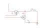
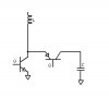
if you run a current through a coil, you create a magnetic field, and when you remove the current this magnetic field collapses and creates a voltage spike?
or something like that

what i would like to know is, what would be THE most efficient way to switch the current. So that as soon as the power is removed (which is coming from a main battery/power terminal), the greatest amount of energy can be obtained/stored (eg in capacitor bank/batteries etc... ) from the spike, with as little loss as possible.
And what would be the most effective storage medium?

Thanks alot
Kane
 
The most efficient switch is mechanical but the life of a mechanical switch is not long, so the next best thing is a transistor. Depending on the frequency of switching, a bipolar transistor can be very efficient, altho mosfets are popular nowdays. At high frequency, it takes a lot of power to drive the input capacitance of a mosfet, so a bipolar might be a good tradeoff in some cases. Power loss in the transistor is due to the finite switching time and the voltage drop when "on". To minimize I squared R losses, make the main battery voltage as high as possible.

When voltage is applied to the coil, the current increases exponentially, eventually reaching the point where the iron in the core saturates. The coil then looks like a short circuit and produces smoke and fire, so you don't want to go that far. The energy stored in the coil (inductor) is 1/2L*I^2, so you have to compromise between I^2*R losses and I^2*L storage.

For long term output storage, use a battery. Or, for short term storage, a capacitor with high peak current and low resistance ratings will work. Or, use both, because the battery probably has high resistance to high peak currents.
 
What you are describing is a "buck", "boost", or "buck/boost" converter. They are used often and you can do a search to find out a lot about them.

MOSFETs are usually more efficient. The current needed to change the gate charge is an issue, but the current is smaller than a bipolar's base current and the power losses in the current path are usually smaller since it doesn't have the vce(min) limitations of bipolars.

The typical converter circuit uses a diode to switch the current to the output. This creates a voltage drop of 0.3v to 1v. For max efficiency, this is replaced with another MOSFET switched opposite the main switching transistor.

The inductor core losses may be your greatest issue. This is not a simple matter to design.

What do you want to do? You can use a battery, capacitor, or sometimes just feed the current pulses straight to the load.
 
hi guys
thanks for the replies,
it seems mofsets will be the better option then.

but just a couple of queries (as im pretty new to electronics)

The energy stored in the coil (inductor) is 1/2L*I^2, so you have to compromise between I^2*R losses and I^2*L storage.

ok so the first equation is to calculate energy storage, L being inductance? and I being current?

what do the second and last equation show? ... losses in the whole circuit?
and what is the storage equation showing?

If the input pulse is only a few milliseconds, is there anyway to calculate how long the output pulse would last, and how great the current/voltage would be?


thanks alot
Kane
 
An inductor with fixed voltage applied has its current increase until limited by the resistance. The increasing current produces a back EMF that opposes the current increase, resulting in an exponential approach to the V/R limit. The time to reach 63% of the current limit is known as the time constant (Tau). The equation is Tau=L/R where L is the inductance in Henries and R is the resistance in Ohms. For short times relative to Tau, the current increase is linear and is given by: delta I/delta T = V/L.

Now, knowing the peak current, the stored energy can be computed from: (1/2)*L*I^2. If a capacitor is used to collect the energy, its equation is: stored energy = (1/2)*C*V^2. At this point I am getting in over my head! You can't transfer all of the energy of the inductor to the capacitor, but I don't know how to figure it.

When you try to stop the current flow in the inductor, the voltage tries to go to V=L*(delta I/delta T). This can be a very high voltage if the time is short. But, the current flowing into the capacitor produces a back EMF that limits the voltage and extends the time of current flow.

A SPICE simulation is the best way to analyze this circuit.
 
so a simple circuit like this would work?
 

Attachments

  • circuit-i.jpg
    circuit-i.jpg
    8.6 KB · Views: 351
No. I think you intend to charge L1 thru Q1 and charge C1 thru Q2 but that won't work because the current thru L1 is going to ground which is the wrong direction for Q2. Q2 must be a PNP and C1 will charge to a negative voltage.
I recommend this arrangement which will give a positive output.
 

Attachments

  • switch_150.jpg
    switch_150.jpg
    50.2 KB · Views: 354
I don't think you can do anything with the flyback current to improve the efficiency. With the diode across the inductor (the standard scheme), the battery current ceases immediately when the diode starts to conduct. If you direct the diode current elsewhere, that current must come from the battery in order to complete the circuit, so you haven't gained anything.
 
Status
Not open for further replies.

New Articles From Microcontroller Tips

Back
Top