Electro Tech is an online community (with over 170,000 members) who enjoy talking about and building electronic circuits, projects and gadgets. To participate you need to register. Registration is free. Click here to register now.
Welcome to our site! Electro Tech is an online community (with over 170,000 members) who enjoy talking about and building electronic circuits, projects and gadgets. To participate you need to register. Registration is free. Click here to register now.
Suraj,
I used to place a small thick trace at 45 degrees on either side. but a direct triangle of course can be tried and saved as a pad for future use.
regards
sarma
vu3zmv
I have a problem.I start downloading the newer version of eagle.It has been goverened by a new company called AUTODESK.The never version I downloaded 8.2.2.
It is very annoying & its very hard over previous cadsoft versions.Specially adding new libraries, UI icons etc...
Please tell me will I do my work with my old CADSOFT versions or shift to Annoying AUTODESK version?
Nice that you installed autodesk and trying that too, Suraj.
Mine was a crude eagle version 7.7.0 on win XP
BTW, I admire the very fiurst reply.
using polygon. As Ronsimpson rightly advised, The polygon itself would be named same as track #so that it merges wit it.
Thanks entire team who worked on this and I have much to learn.
regards
sarma
vu3zmv
Keep in mind, as you make a branch such as shown, you also make a discontinuity. Depending on the transition speed of signal on the trace, you may find excess ringing due to impedance mismatch. The added triangle however will add capacitance may work to your advantage as it will slow some of the higher speed components.
If this is a clock signal, I would avoid the T-branch, and instead make a daisy chain connection. What I mean is > trace--------o--------o------- termination. where the o represents a load. instead of the t branch ----|----
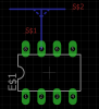
I did as you all mentioned.Changed the polygon name, but nothing happened.Eagle version is 7.6.0.
Here how I did.
1. Using Wire tool draw two wires to make a T joint.
2. The default wires names are attached in the picture.
3. Using polygon tool draw a triangle over the joint.
4. Using the Name tool change the polygon name to “S$2”.
5. Click Ratnest.
6. Nothing happened the triangle still like earlier
This site uses cookies to help personalise content, tailor your experience and to keep you logged in if you register.
By continuing to use this site, you are consenting to our use of cookies.