Continue to Site

Welcome to our site!

Electro Tech is an online community (with over 170,000 members) who enjoy talking about and building electronic circuits, projects and gadgets. To participate you need to register. Registration is free. Click here to register now.

  • Welcome to our site! Electro Tech is an online community (with over 170,000 members) who enjoy talking about and building electronic circuits, projects and gadgets. To participate you need to register. Registration is free. Click here to register now.

Ducted A/C Communication protocol

Status
Not open for further replies.

josh6899

New Member
Hi all, i'm very new with electronics, looking to get a better understanding.
I work as a HVACR tech and I've been looking into making an Arduino thermostat to use mainly on Panasonic's ducted inverter A/C.

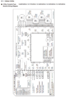
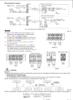
The issue i'm facing is that i don't know how the controller talks to the indoor PCB, there's 2 wires and they connect to terminals "R1, R2" which is between 12v-16v DC. I understand that it sends 12v DC to power the thermostat but is there some kind of Pulse width modulation to communicate with the system ?

If we can figure out how the RC communicates with the PCB then it should be possible to make an Arduino communicate also.

I've included some data sheets.

Any suggestions on this will be greatly appreciated
 

Attachments

  • Diagram.PNG
    Diagram.PNG
    162.7 KB · Views: 271
  • RC.PNG
    RC.PNG
    268.4 KB · Views: 277
So basically I found out that the controller does key scan information from each button and transmits that information (binary code I believe "1's and 0's" on top of the 12v DC line.

So understanding what each buttons binary code is, that will represent a certain function when transmitted to the main PCB .

Now I have no idea how to measure or read such information.... Any ideas ?
 
From those diagrams, both units have their own power so the interconnection is most likely data-only.

The diagram shows the connection as two core plus screen, so there is also a common 0V link between the units.
Possibly RS485, or CAN bus, though it could be their own unique system.
 
The datasheet says the devices have to be connected in a daisy chain (no loops, no branches of the bus) - not a requirement of CAN Bus. Each unit has a R1/R2 input and U1/U2 output to the next unit in the daisy chain - the datasheet says branches cause addressing issues so I assume each unit gets an address assigned dynamically on system power-up.
 
I don't know as it will help?, but an old friend and ex-collegue of mine has been living in Hong Kong for a good long while now, last I heard he was involved in retro fitting control system for air-con in hotel rooms - the system used the existing TV aerial distribution to carry the control signals both ways. The system also used the existing air-con units in the rooms, so presumably must have had some kind of interface to work with multiple types of equipment.

The paper work above shows IR remote control receivers, commonly when that is used it's often also used for the wired control as well - using the same IR signals, but without the modulation.

As others have said, you need a scope to examine the signals, and see what they look like.
 
Each unit has a R1/R2 input and U1/U2 output to the next unit in the daisy chain
Look again - the indoor <> outdoor unit link is on the U1-U2 terminals of both.

The R bus is for a wired remote control panel / thermostat, rather than main unit interconnections.

A page for a commercial large system interface, which gives the limit as 64 indoor units and 30 outdoor units on each U bus network:

An from the same place, a home automation interface that uses the R bus:
 
RS485 ish.

Carrier has an ABCD bus. 2 are power and 2 are RS485 2-wire. That connects all of their junk together.

Their outdoor unit can use conventional signals. The furnace CAN use conventional signals.
 
Status
Not open for further replies.

Latest threads

New Articles From Microcontroller Tips

Back
Top