giftiger_wunsch
New Member
Hi,
I thought I'd post the schematic for my microprocessor power supply circuits here and see if I could get some opinions / suggestions for improvements.
Notes:
I'm using a power connector mounted in the rear of the project box containing the board, and as is hopefully clear from the schematic, the battery pack will power the board when it is not plugged in, and will be switched off by the relay when the wall-wart supply is available. The master power switch and the LED power indicator are both mounted in the front of the project box.
I'm new to electronics and especially to using microcontrollers / microprocessors, so I may have made a couple of mistakes with the schematic.
Thanks in advance for any help.
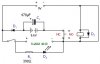
I thought I'd post the schematic for my microprocessor power supply circuits here and see if I could get some opinions / suggestions for improvements.
Notes:
- The board power supply should be 8-30VDC.
- The DC supply at the top is actually a 6V unregulated wall-wart, but usually delivers around 9-10V and has been sufficient to power my board so far. I'm hoping to replace it with a 12V regulated supply when I can find a cheap one.
- The battery is a battery holder containing 8 x 2800mAh 1.2V AA NiMH batteries. I was originally considering integrating a charger into this circuit, but trickle-charging would be slow and the batteries can easily be removed from the battery pack and charged in my high-speed commercial charger within a couple of hours. Also this would of course make it all the more necessary to obtain a higher voltage wall-wart supply.
- The relay is a SPDT 5VDC sub-miniature with a coil resistance of 100Ω ± 10%
I'm using a power connector mounted in the rear of the project box containing the board, and as is hopefully clear from the schematic, the battery pack will power the board when it is not plugged in, and will be switched off by the relay when the wall-wart supply is available. The master power switch and the LED power indicator are both mounted in the front of the project box.
I'm new to electronics and especially to using microcontrollers / microprocessors, so I may have made a couple of mistakes with the schematic.
Thanks in advance for any help.
Attachments
Last edited:
