Continue to Site

Welcome to our site!

Electro Tech is an online community (with over 170,000 members) who enjoy talking about and building electronic circuits, projects and gadgets. To participate you need to register. Registration is free. Click here to register now.

  • Welcome to our site! Electro Tech is an online community (with over 170,000 members) who enjoy talking about and building electronic circuits, projects and gadgets. To participate you need to register. Registration is free. Click here to register now.

dual circuit delay off flashing relay

Status
Not open for further replies.

heliguy

New Member
Hi all
I'm just passing through in the hope that you guys can help me.
I'm wondering if there's an electronic solution to my Harley problem.
I'll try and explain I have fitted new handlebar controls and the turn signal wiring is different.

Here is what I have.

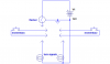
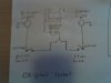
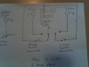
one wire coming from each side of the bars (1-left turn/1-right turn)
they supply +12dc through a momentary switch.

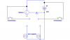
these have to function as a regular indicators would or maybe time of after a preset time.

I think I could do this with 2 flashing relays and six relays.
but there just not enough space for this.


Anyways I hope there is enough info if not, ask and ye shall recive

I hope this sparks an interest and you have some fun figureing it out.
either way nice site and best of luck to you all
 
by indicators, do you mean turn signals? You want these to flash for some preset period of time and then shut off? It could be done with 2 flashing relays and a little circuitry or with more effort, no relays at all. what are you looking for? also, what is the current rating on the turn signal lamps?

But, I have to believe that there are pre-made replacements for this.
 
Yes I mean turn signals
yes flash for preset and then turn off.
the ideal would be no relays (limited space)
2x20watt 12v bulbs

I have searched the web for something to do this, with no luck
on the bike forums the responce is, if I figure it out to please let them know
so I guess its a common issue.

thank you for a glimmer of hope
 
Have you seen this? Do you not have a turn signal flasher already? I'm still not clear why you have a problem. You said you have momentary switches. Are you saying that they will not stay latched on? Were they meant to be depressed for as long as you want to signal, because motorcycles have no means of self-cancellation such as cars have?
 
Ron H said:
Have you seen this? Do you not have a turn signal flasher already? I'm still not clear why you have a problem. You said you have momentary switches. Are you saying that they will not stay latched on? Were they meant to be depressed for as long as you want to signal, because motorcycles have no means of self-cancellation such as cars have?


I looked at these units but as far as I can make out they depend on the switch latching, they then turn off even though the switch is still on.

The bike as standard had a 2pole flashing relay. the body picked up -12vdc from the mounting. one of the poles +12dc from the ignition (permanent on while the ignition is on) the last pole had 2 wires connected, 1 to each turn signal switch (that latched on) the other side of each switch had a wire to the appropriate side lights.
it worked like this -power entered the relay and waits till a switch is latched then the circuit is completed for that side and flashing begins and when your done turn the switch off.
The new set up handlebars with controls pre wired with cables through the bars(and not a hope of running an extra cable through) share power in the bars so I end up with 2 wires in the junction box(the headlight) that are either on or off. the new switches are spring loaded momentary contact.
I thought about getting a 2nd relay and just holding the switch, it would work but I think it would be dangerous.There's a lot going on when turning a bike the last thing you need is to be trying to hold the switch on.

The options to get around this that I can think of are:
1:a latching circuit with pulse on pulse off x 2(I use the original relay x 2)
2:a latching circuit with timer off x 2 (I use the original relay x 2)
3:a latching circuit with pulse on pulse off with flashing output x 2
4:a latching circuit with timer off with flashing output x 2
5:I use the original relay x 2 and get used to holding it on
I'm sure there are other ways of doing it that I can't imagine.

Thanks for your interest
 
Last edited:
So is this what you now have?
Do you have the skills to read a schematic and build a little circuit (soldering, etc.)?
 

Attachments

  • turn sigs.PNG
    turn sigs.PNG
    8.4 KB · Views: 285
Yours is right except I dont have access to one side of the switch terminal it is connected to live and I cannot change this.
heres some circuit layouts there not as tidy as yours but they will explain what I cant put into words.
In the what i Have now pic the terminals that look like they are not connected are not. they are in the junction box waiting for me to make a disision on were to go next.

I should have no problem reading a schematic and building a little circuit.
 

Attachments

  • 18-05-06_1818.jpg
    18-05-06_1818.jpg
    14.7 KB · Views: 248
  • 18-05-06_1819.jpg
    18-05-06_1819.jpg
    15.4 KB · Views: 248
Last edited:
So the switches are hardwired to the plus side of the battery because there are other switches in the handlebars that use +12V, like the headlight switch?
I think we can come up with something. Do you have room for a little circuit board somewhere, maybe a couple of inches square by 1 half inch high? This is what you would have to build.
 
yep bang on (headlights/ horn /brake light)
The cables all come back to the headlight so that size should be ok.
thank you
 
I was thinking each side would have 2 555s (or 1 556). the first for the duration and the second for the flashing rate. then a mosfet to drive the lamps. there may be a way to have one set of timers for both sides and switch which lamp gets driven. trimpots for the duration and flashrate. Steady state current on a 20W lamp is about 1.66A - a lowish Rds (.01), an approx 50% duty cycle and infrequent use might mean no heatsink required. I don't know what the inrush effect would be in the flashing situation.
 
Here's my shot at your latch/timer. It's more complex than I had hoped, and could be done (I think) more simply with a microcontroller. Unfortunately, unless you have a programmer and programming skills, or a friend who does, it is probably not practical for you.
There are actually only 3 integrated circuits here, in addition to the discrete components.
I hope you can expand the schematic enough to read it.
 

Attachments

  • turn signal latch and auto-off2.PNG
    turn signal latch and auto-off2.PNG
    61.3 KB · Views: 724
Last edited:
Hi Ron H
Couple of questions
Can resistors r4,r5 be changed to altar duration.
are r1,r13,c1,c8 absolutely necessary or can they be moved as I have no access to that side of the switch.
the value for a1,a2... appear to be a 4/4 CD4011 and 4/z CD4013 I'm not sure what this means. will the guy at the parts counter know

edit: ok I think this means part CD4011 4 of 1 , 3 of 1....
and CD4013 part 2 of 1 part 1of 1
is this correct
 
Last edited:
Is this part list correct
Resistors
10k X 7 rs 148-736
100k X5 rs 148-972
1meg X 1 rs 149-228

Capacitors
100nf X 4 rs 211-5491
1nf X 1 rs 211-4779
1uf X 1 rs 267-4798
47uf X 2 rs 267-7270

Diode's
1N4148 X 3 rs 436-7341

Nand gate
CD4011 X 1 rs 787-369
CD4013 X 1 rs 355-8300

Timer
Lmc555 X 1 rs 534-4002

Mosfet
IRF7404 X 2 rs not available would something else do

Can you say if I got this right the part numbers are from http://www.radionics.ie
 
Last edited:
heliguy said:
Hi Ron H
Couple of questions
Can resistors r4,r5 be changed to altar duration.
are r1,r13,c1,c8 absolutely necessary or can they be moved as I have no access to that side of the switch.
Oh yeah, I forgot. See revised schematic.
the value for a1,a2... appear to be a 4/4 CD4011 and 4/z CD4013 I'm not sure what this means. will the guy at the parts counter know

edit: ok I think this means part CD4011 4 of 1 , 3 of 1....
and CD4013 part 2 of 1 part 1of 1
is this correct
Yeah, that 4/z is actually 1/2. I should have used a bigger font.
I also added a couple of wires to lock out the possibility of both signals being on simultaneously. See schematic above.
 
heliguy said:
Is this part list correct
Resistors
10k X 7 rs 148-736
100k X5 rs 148-972
1meg X 1 rs 149-228
The 1meg is a potentiometer. Use 375-023, or select one with a shaft if you want a knob on it.

Capacitors
100nf X 4 rs 211-5491
1nf X 1 rs 211-4779
1uf X 1 rs 267-4798
47uf X 2 rs 267-7270
You can use 267-4631 (less expensive, maybe smaller).

Diode's
1N4148 X 3 rs 436-7341

Nand gate
CD4011 X 1 rs 787-369

I screwed up. This should be CD4001, a quad NOR gate.
CD4013 X 1 rs 355-8300
Those are both in surface mount packages. The DIP14's are easier to handle if you don't have a PC board, but consume more space.

Timer
Lmc555 X 1 rs 534-4002
Package is unspecified.

Mosfet
IRF7404 X 2 rs not available would something else do
Do you want this in a surface mount package, or a through-hole package? I think we can find something that will work.

Can you say if I got this right the part numbers are from http://www.radionics.ie
See my notes above in red.
You asked if R4 and R5 can be used to vary the duration. See the note on the schematic beside R4, which is a variable resistance.
Did you see the button in the lower right corner of the schematic that allows you to expand it? Sometimes you have to wait a few seconds for it to appear. You can also save it and open it with picture manager or whatever. Either way will give better resolution.
 
Last edited:
I think through hole is the way to go.
that was an error on my part.

the updated list
Resistors
10k X 7 rs 148-736
100k X5 rs 148-972
1meg X 1 rs 522-0912

Capacitors
100nf X 4 rs 211-5491
1nf X 1 rs 211-4779
1uf X 1 rs 267-4798
47uf X 2 rs 267-4631

gate's
CD4001 X 1 rs 306-522
CD4013 X 1 rs 306-550

Diode's
1N4148 X 3 rs 436-7341

Timer
Lmc555 X 1 rs 346-1975

Mosfet
IRF7404 X 2
 
Last edited:
Change the MOSFETs to IRF5305.
I didn't check everything this time, but I think you're good to go.
 
I will order the parts and let you know how it goes.
I have been looking at diy pcb kits, it looks interesting so I might give that a try.
Thank you
The generosity of strangers always amazes me.
 
Status
Not open for further replies.

Latest threads

New Articles From Microcontroller Tips

Back
Top