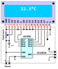
Continue to Site

Welcome to our site!

Electro Tech is an online community (with over 170,000 members) who enjoy talking about and building electronic circuits, projects and gadgets. To participate you need to register. Registration is free. Click here to register now.

  • Welcome to our site! Electro Tech is an online community (with over 170,000 members) who enjoy talking about and building electronic circuits, projects and gadgets. To participate you need to register. Registration is free. Click here to register now.

DS18B20 with pic

Status
Not open for further replies.
That should work as a fine starting point, although I don't see the point of just copying and pasting code, read it through, understand what it is doing and come up with your own methods, strike a balance though, there's no point in reinventing the wheel. I vaguely remember seeing a Microchip Application note on using 1wire, check their web site for information. There are loads of tutorials around the web on using LCD character displays, it's all explained pretty clearly in the datasheets for these things anyway, but I think Nigel might have a tutorial on using them, if you have a look here .

rgds
 
Here's an assembly language example for a 16F690. I hope it helps.

Regards, Mike
 

Attachments

  • DS18B20 + LCD.PNG
    DS18B20 + LCD.PNG
    13.3 KB · Views: 2,109
  • AAC 690+LCD.ASM.TXT
    22.3 KB · Views: 846
thanks to all the users above for providing the links.... but i don't have pic16f690 i just need the temp to be displayed on 16x2 lcd i searched in Google i got some circuits but its all using seven segment display...or its using atmel and to tell you guys i am just a electronic hobbyist....
 
Hi,

Sounds more like you want all the code ready done for you ..?

If you go though Nigels tutorial and program / build the lcd section then you will soon see how you can extract just the Ds18b20 routine from those other programs mentioned and add it to your own code to make exactly what you want.

As you can see from Jake long post on his ds18b20 project there is always plenty of help here if you get stuck on a particular point.

If you do continue down the ds18b20 route then these encased versions are good value - use them myself.
**broken link removed**

Hoiwever to get you going quicker have you thought about using the much simpler LM35 sensor - again widely covered in this forum.
 
digital thermometer cadsoft eagle

hii i got the digital thermometer circuit i have also attached my eagle schematic can anyone please check my sch??? the problem here is when i convert to the board i am not able to find the power input solder pads.... please help.

sorry my English isn't good...
 

Attachments

  • digital therm.sch
    149.6 KB · Views: 379
  • Date_time_day_temp.zip
    116 KB · Views: 438
even i am planning to build digital thermometer its good that i found this post..it seems the sch is correct why don't you do it on the strip board as the circuit is simple....
 
I have recently completed this in boostc on a 18f4520 dev board.

It was very painful as there is loads of assembler out there, but very little C.
But using other peoples well commented code as a basis, does help you to understand the process and recreate it. Look for one wire functions in your version of C and either use these or alter for assembler.

When you can understand it and it can be alterd as you need.
I now have two DS18B20 on one board with readings displayed on LCD, did cheat though and put them on two seperate ports to get around using the rom code read functions (so still to do)
 
Last edited:
Status
Not open for further replies.

Latest threads

New Articles From Microcontroller Tips

Back
Top