jakeselectronics
Member
Hello everyone.
Back in May I started a Digital Thermometer Project using the Dallas 18B20 sensor and a PIC16F268A using assembly language.
Firstly thanks to Mike K8LH, Pommie, Nigel Goodwin, and Dougy for their immense help throughout.
I am revisiting this project because I never 100% completed it.
After what I though was finishing it, I realized when the temp hit roughly 40c, the program froze.
I have managed to fix that bug and have tested it to its full range. Works perfectly from -55 to 127.
The issue I have is display flicker.
It is the slightest random shimmer over the LED display.
Just enough for the human Persistence of Vision to pick up.
Project Background:
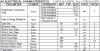
Digital Thermometer using DS18B20 12-bit mode (.1 degree resolution)
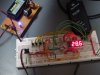
Display is LED 4 digit 7 segment.
Program simply gathers data from Temp Sensor and
Uses Timer 2 interrupt to refresh LED display.
Pommie helped me out with a little routine that would wait for the interrupt to finish before the time crucial communication started.
This was only because disabling and re-enabling interrupts wasn't working for some reason.
But now it is after many changes, and I would like to continue using disable and re-enable interrupt instructions to prevent the interrupt during communication.
What I am asking is for fresh eyes to look over the program to try to lower the ratio of time that interrupts are disabled to stop the display flickering.
Basically, I have a Working program, but it needs code optimization.
Any tips???
Here is the ASM (to big to wrap in code tags)
DS18B20 Digital Temperature Sensor.asm
Schematic:
http://www.jakeselectronics.net/projects_digitaltemperaturesensor.php
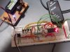
Breadboard:
http://www.jakeselectronics.net/projects_digitaltemperaturesensor.php
edit: project finished, amended links to finished project
Back in May I started a Digital Thermometer Project using the Dallas 18B20 sensor and a PIC16F268A using assembly language.
Firstly thanks to Mike K8LH, Pommie, Nigel Goodwin, and Dougy for their immense help throughout.
I am revisiting this project because I never 100% completed it.
After what I though was finishing it, I realized when the temp hit roughly 40c, the program froze.
I have managed to fix that bug and have tested it to its full range. Works perfectly from -55 to 127.
The issue I have is display flicker.
It is the slightest random shimmer over the LED display.
Just enough for the human Persistence of Vision to pick up.
Project Background:
Digital Thermometer using DS18B20 12-bit mode (.1 degree resolution)
Display is LED 4 digit 7 segment.
Program simply gathers data from Temp Sensor and
Uses Timer 2 interrupt to refresh LED display.
Pommie helped me out with a little routine that would wait for the interrupt to finish before the time crucial communication started.
This was only because disabling and re-enabling interrupts wasn't working for some reason.
But now it is after many changes, and I would like to continue using disable and re-enable interrupt instructions to prevent the interrupt during communication.
What I am asking is for fresh eyes to look over the program to try to lower the ratio of time that interrupts are disabled to stop the display flickering.
Basically, I have a Working program, but it needs code optimization.
Any tips???
Here is the ASM (to big to wrap in code tags)
DS18B20 Digital Temperature Sensor.asm
Schematic:
http://www.jakeselectronics.net/projects_digitaltemperaturesensor.php
Breadboard:
http://www.jakeselectronics.net/projects_digitaltemperaturesensor.php
edit: project finished, amended links to finished project
Last edited: