Continue to Site

Welcome to our site!

Electro Tech is an online community (with over 170,000 members) who enjoy talking about and building electronic circuits, projects and gadgets. To participate you need to register. Registration is free. Click here to register now.

  • Welcome to our site! Electro Tech is an online community (with over 170,000 members) who enjoy talking about and building electronic circuits, projects and gadgets. To participate you need to register. Registration is free. Click here to register now.

Drum switch

Status
Not open for further replies.

Gregory

Member
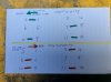
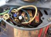
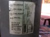
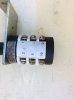
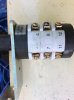
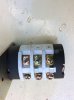
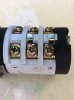
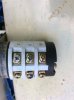
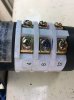
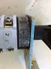
I have a drum switch and a singel phase 240 v AC motor.
I have the 2 wires I require to switch to obtain forward and reverse .
Could you advise me how to wirer the drum switch to the motor to obtain forward and reverse.
I have posted photoes of the motor and drum switch.
 

Attachments

  • IMG_2188.JPG
    IMG_2188.JPG
    1.2 MB · Views: 140
  • IMG_2189.JPG
    IMG_2189.JPG
    1.1 MB · Views: 143
  • IMG_2190.JPG
    IMG_2190.JPG
    483.3 KB · Views: 128
  • IMG_2191.JPG
    IMG_2191.JPG
    533.1 KB · Views: 146
  • IMG_2192.JPG
    IMG_2192.JPG
    491.7 KB · Views: 131
  • IMG_2193.JPG
    IMG_2193.JPG
    499.6 KB · Views: 128
  • IMG_2194.JPG
    IMG_2194.JPG
    400.4 KB · Views: 129
  • IMG_2195.JPG
    IMG_2195.JPG
    512.1 KB · Views: 127
  • IMG_2196.JPG
    IMG_2196.JPG
    497.4 KB · Views: 140
Firstly your switch doesnt look like a reversing dewhurst type switch, it looks like a 2 speed selector.
Here in the Uk the colour code may well be different so what I say may not apply.
The red & black or A & Az are usually the run winding, the other 2 wires going into the windings part of the motor are most likely the start winding, I see in the pic there is a centrifugal switch.
Reversing the polarity of the start winding in respect to the run winding reverses a motor of this type, to do this you need a double pole change over switch, it may be possible to do that with the switch you have, you'd have to check it with a continuity tester to find out what contact arrangement it has.
You should also meter out the windings of the motor before you try to run it.
 
Since you are just reversing the start winding, the motor needs to be stopped before reversing it. Otherwise, it will continue to run in the original direction, perhaps with a little different sound.
 
The blue and white wirer that are disconnected if they are swapped around then the motor will go from forward to reverse.
I have connected the drum switch and I am able to go one direction and turn off.
How do I wirer the drum switch now to revers the 2 wires .
What information is require to enable you to help me with this problem.
 
I'm not sure you can as the switch looks as though its for 2 speed not reversing, the only way you could tell if it is possible is with a meter and some knowledge, you need to see if there is 2 sets of contacts that change over when you flip the switch.
Its unlikely any problem would arise reversing direction whil the motor is running, the centrifugal switch disconnects the start winding while the motor is running, so long as you dont try and reverse while the motor is starting.
 
I have don a continuity test and documented to enable you to draw up a circuit for me.
 

Attachments

  • IMG_2198.JPG
    IMG_2198.JPG
    988.1 KB · Views: 152
I am making the assumption that the switch has a centre off position where there is no continuity between any of the connections. If this is the case then this way of connecting the switch should work.
201117.jpg


This needs 6 wires between the switch and motor. If you can identify which terminals in the motor are the main winding, the start windin, the centrifugal switch and the start capacitor. (If fitted.) then only 4 wires would be required between the switch and the motor.

Les.
 
You ar correct there is neutral position in the centre.
Thank you for the drawing as I will wirer it up tomorrow.
 
I had prepared some more instructions on metering out the connections, but I see you already have answers.
Super.
 
As long as 9 to 10 and 11 to 12 are open in the off position it does not matter what state the other four contacts are in. I think you will be ablwe to use the metal strap removed from between 9 and 11 to connect 1 to 3. You can leave the strap between 5 and 7.

Les.
 
Les Jones and other members thank you for your advice . I have wired up the motor and the motor workes very well.
Have a merry Christmas and all the best for the new year
Greg.
This Forum is very helpful to me and others Well done
 
Status
Not open for further replies.

Latest threads

New Articles From Microcontroller Tips

Back
Top