Continue to Site

Welcome to our site!

Electro Tech is an online community (with over 170,000 members) who enjoy talking about and building electronic circuits, projects and gadgets. To participate you need to register. Registration is free. Click here to register now.

  • Welcome to our site! Electro Tech is an online community (with over 170,000 members) who enjoy talking about and building electronic circuits, projects and gadgets. To participate you need to register. Registration is free. Click here to register now.

DRO Interface

Status
Not open for further replies.
I am using units like this one to get digitized values for the machines in my workshop:

51059710553_90350920bd_o.jpg


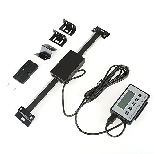
What I have yet not found is the kind of interface to the display and control unit is being used here. I want to use an ESP32 board to gather the digital data from the sensor and use a HMI of my own design on a normal display so that X-, Y-, Y- and Angular-Data can be displayed. The EPS32 additionally allows it to connect to display and/or PC via Wifi and/or Bluetooth.

Health and best wishes for 2022
Hellmut
 
Interfacing directly to the scale (or encoder) they use is usually simple enough; it's typically just a quadrature signal that counts the scale steps.

The display unit is a different matter; it's probably simpler to recreate one than modify an existing one that does not have facilities for ab external output.
You should also be able to tap in to the scale signal and feed a separate unit at the same time as the display box.
 
The scales in the picture look like ones made by a company called iGauging. They are not quadrature scales.
Here is some information on the original iGauging scales but I have heard that newer ones use a different protocol.
iGaging (21 bit)

LSB sent first
The 21 bits are all used as a 21 bit binary number. (No bits used as flags.)

Static state of clock line between frames Low
Static state of data line between frames
Time between start of frames 7 mS
Length of data frame about 2.33 ms
Interrecord gap about 4.67 mS
Time between clock pulses about 111 us (Clock cycle time.)
Time clock pulse is negative about 89 uS
Time clock pulse is positive about 22 uS
High level at start of frame about uS


Clock in the data on the negative going edge.

CPI 2560

21 bits in a frame of data

You will need to look at the data and clock signals between the scales and the display unit to identify the protocol being used.
Here is a link to an interface I built for reading the original iGauging scales and some protocols used on some other Chinese scales that also includes links to other information on DROs.
http://lesjhobbies.weebly.com/interface-for-yuriys-android-dro.html

Les.
 
Thx to both responders. I am currently very busy building a lot of stuff for my workshop. But your responses say to me that y should not have the milling Optimum BJ 20L, but to proceed using scales as the one shown to implement digitized positioning as I expect to be later making such a display.

Is there DRO that is less expensive or that is easier to read out into a DIY display?

Best regards and stay healthy
Hellmut
 
Is there DRO that is less expensive or that is easier to read out into a DIY display?
Those kits are ludicrously cheap already!

You can easily buy scales with quadrature signals that may be easier to interface - eg. this listing does multiple sizes and even gives the connector pinouts:

I've never seen cheap DROs with external interfacing; it does not mean they do not exist..
When I've needed to interface with a DRO for a control system, it's always been by intercepting the scale or encoder signals and replicating the counters etc. in software.
 
Status
Not open for further replies.

Latest threads

New Articles From Microcontroller Tips

Back
Top