Continue to Site

Welcome to our site!

Electro Tech is an online community (with over 170,000 members) who enjoy talking about and building electronic circuits, projects and gadgets. To participate you need to register. Registration is free. Click here to register now.

  • Welcome to our site! Electro Tech is an online community (with over 170,000 members) who enjoy talking about and building electronic circuits, projects and gadgets. To participate you need to register. Registration is free. Click here to register now.

Driving Higher Voltages from PIC 16F88

Status
Not open for further replies.

Tom81

Member
Hi all,

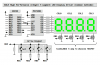
I'm using a PIC to drive a 7-Segment LED circuit. The Micro can supply 5V, but each segment needs 8V/20mA to switch on and off...

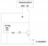
Before I wire the circuit up to the micro, I've been running a few tests on a breadboard, using a 8V power supply and a 7805 5V Regulator.

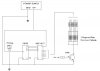
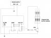
What's the best way to switch a segment on/off? I tried to use a BC548 NPN Transistor, with +5V going to the base via a 1K resistor, and +8V going to the segment (via the NPN), but it doesn't seem to like that (see attached).

All the grounds are tied together, which I suspect could be the source of the problem. Any thoughts?

Please help!

Thanks,
Tom
 

Attachments

  • PIC1.JPG
    PIC1.JPG
    35.4 KB · Views: 567
You need both an NPN & PNP transistor per segment (should have bought CA displays)
(I couldn't find a NPN / PNP version with a quick google search) but it's similar to the image below.
**broken link removed**
 
You need to either,
change the NPN to a PNP and swap C and E around.
Or,
Swap the segment and the transistor, so the segment is between C and +8V.

You should also add a current limiting resistor in series with the segment.

Mike.
 
blueroomelectronics - Thanks for that. I did see a similar circuit on the net, but I was hoping to get away with less components.

Mike - I'll give it a crack when I get home. Thanks again

-Tom
 
You need to either,
change the NPN to a PNP and swap C and E around.
Or,
Swap the segment and the transistor, so the segment is between C and +8V.

You should also add a current limiting resistor in series with the segment.

Mike.
PNP can never be turned off with the base 5 V and the emitter 8 V.

*EDIT: For more than 5 V, use common anode with PNP coupled with NPN.
 
Last edited:
You might consider using one of the high side driver or sourcing driver ICs. Connect your 8-9 volt source to the Vs pin on the UDN2981.

hi-side-driver-png.32506

Connect your 8-9 volt source to the VBB pin on an MIC5891 serial-to-parallel sourcing driver IC.

hi-side-driver-2-png.32508
 

Attachments

  • Hi-Side Driver.PNG
    Hi-Side Driver.PNG
    30.4 KB · Views: 4,495
  • Hi-Side Driver 2.PNG
    Hi-Side Driver 2.PNG
    40 KB · Views: 6,980
Last edited:
Hi Mike K - circuit looks good, and straightforward too. Although I'm not sure where I can get UDN2981 at short notice. I'm sure there's an equivalent available in Oz.

As an alternative, I've got a 4511 BCD to 7-SEG Latch/decoder driver kicking around somewhere. Unbeknownst to me, turns out these can handle up to 15V. I'm thinking if I use 8~9V as Vdd to the decoder, I might be able to get away with feeding the four data pins with 0-5V straight from the Micro. Whether 5V (as a data input to the 4511) will register as a 'Logic 1' is another question... if it does, it would make life a lot easier in compenents and I'd save on port pins from the micro too. Then I can just use the NPN's as switching (as per the circuit above).
 
You can get the UDN chip from **broken link removed** for AU$2.97 but allow at least a week for delivery.

Mike.
 
Thanks for everyone's input. Attached you'll find the circuit I ended up using (minus a few components). I would have liked to have used the UDN chip (I really needed to have control over each segment so I could display letters as well as numbers). I needed something sooner though, so I went with the 4511.

Some things to note about the circuit: I've omitted filtering capacitors, largely because I'm lazy. I put one either side of the Regulator, and a couple for the PIC.
For PIC timing/accuracy I used a 4MHz crystal (also not shown).
You'll need to tie some of the function pins on the 4511 to +V or ground, depending on how you use it. I can't recall which pins. Best to check the data sheet.
There are four LED-displays in total, although for simplicity, there's only one on the ciruit.

I measured my Voltage supply at 9.3V. The datasheet for the Led-display indicates 8.8V maximum supply voltage for each segment. Conveniently there's a small V-drop across the 4511 (around .8V I think), so that worked out nicely. Again, you can check the datasheet for this.

-Tom
 

Attachments

  • BOARD002.jpg
    BOARD002.jpg
    36.3 KB · Views: 522
Status
Not open for further replies.

Latest threads

New Articles From Microcontroller Tips

Back
Top