hi,
Yes I had a look at the datasheet. You are saying that the CCP pins should be connected to 1A/3A and 2A/4A? But this pins are used for motor direction control and not speed control right?
The PWM rate on these pins control the motor speed.
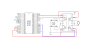
enable 1A 2A Function
H L H turn right
H H L turn left
H L L fast motor stop
H H H fastmotor stop.
This is the table from the datasheet.
So i guess the CCP pins should be connected to the enable pin? Am i right?And I can use and inverter for 2A and use only one PIC pin for each motor..right?
Please correct me if I am wrong. Cheers mate!
")

 Can anyone please help?