Continue to Site

Welcome to our site!

Electro Tech is an online community (with over 170,000 members) who enjoy talking about and building electronic circuits, projects and gadgets. To participate you need to register. Registration is free. Click here to register now.

  • Welcome to our site! Electro Tech is an online community (with over 170,000 members) who enjoy talking about and building electronic circuits, projects and gadgets. To participate you need to register. Registration is free. Click here to register now.

Driving a DC Motor with PIC

Status
Not open for further replies.

Hesam Kamalan

New Member
Hi,
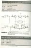
I want to build a Car with PIC and DC Motor. DC motor have two pins. when VCC Connected to first and GND Connected to second, wheels turns right and vice versa.
I think that i can not connect these two pins to PIC ports directly.
tell me how can i drive this motor and how can i control, speed of this motor, please (i want schematic if possible).

regards
 
Use Google or search this forum for "H-bridge". The forum has 18 pages of results.
 
I suggest to use a motor driver such as L293D to drive the motor. Connect the motor winding to the output of L293D( refer to my previous post- Drive a stepper motor with PIC and L293D).
Use one of the port pin from the PIC to generate the Pulse Width Modulation to control the speed of the motor.
Use 2 port pins from the PIC to the enable pins of the L293D to control the direction.

I was going to put a post on this topic. But I am working on a unipolar stepper motor right now. I might change to DC motor speed control first.

:)
 
so easy to make H-Bridge circuit and you will learn too much through making it .

use this schematic i have tested it and it works very well
 

Attachments

  • H-Bridge.jpg
    H-Bridge.jpg
    301.4 KB · Views: 845
You need the diodes in reverse parallel with each transistor. He should have them there but does not. The motor inductance will try to keep current flowing when the transistor turns off. If the diode is not there it will try and "spark" across the MOSFET and damage it. The diode gives this "flyback current" a path to flow.
 
It's good and well to use discret components in your design for learning and fun. But in real world IC are used when ever practical and possible. For example in that diagram, there are more than 10 components, whereas you can use one low cost common driver IC instead. It save space, fewer connections, easier to implement, and less chance to make mistake. Consider if you have a dead line to meet.

:)
 
Status
Not open for further replies.

Latest threads

New Articles From Microcontroller Tips

Back
Top