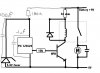
Continue to Site

Welcome to our site!

Electro Tech is an online community (with over 170,000 members) who enjoy talking about and building electronic circuits, projects and gadgets. To participate you need to register. Registration is free. Click here to register now.

  • Welcome to our site! Electro Tech is an online community (with over 170,000 members) who enjoy talking about and building electronic circuits, projects and gadgets. To participate you need to register. Registration is free. Click here to register now.

Drawing too much power turns pic off ???

Status
Not open for further replies.

2camjohn

Member
I have this circuit

**broken link removed**


The problem is as soon as it powers the load (the motor) it starts acting crazy.

I think the current drawn by the motor causes insufficcient power to keep the PIC on, so it turns off and starts its code from the begginning.

This is producing some very strange and annoying problems.

Without the load everything acts fine.


Does anyone have any suggestions for solving this problem?

Thanks in advance,
John
 
Wy don't you try a greater source of power ? With more Amp's or wy don't you use an optoisolator instead of the transistor, you know there are OptoIsolators with SCR's Output or Triac wicth could be the best option for an engine driving, don't forget that the inductor of the ( er i forgot the inglish name, is it Rellay ?? ) also has a capacity and create a discharge every time the transistor outputs an impulse to it that could be making interference in the Pic so use discrete devices instead of mechanical it's rater safe for digital environtment !
The pic also needs a capacitor in parallel with it and it doesn't drains that mutch power lol :D.
 
Thanks for the reply

I can only find opto isolators with an output current of about 300ma.
**broken link removed**

I need to switch more than 1A.


I thought the diode would protect the pic from any interfearnece caused by the relay.


I have tried putting a capacitor in paralell with the PIC, but it doesnt help. What value should i try? I tried 10nf.


What else can do to protect my pic from interfearence?


Thanks
 
for one thing you ABSOLUTELY need a capacitor across the supply terminals of the PIC...

You might also try using a MOSFET to switch the motor instead of a relay, 1A for a mosfet is NOTHING... even mid-range ones are usually rated for like 30A or more, the ones I use are rated for 150A peak

Personally I had a project something like that, using a PIC with two mosfets to switch two solenoids. I am using a 78L05 voltage regulator instead of a zener/resistor, but the idea is the same. What I ended up having to do was to A) use a semi-large capacitor across the PIC supply (330uF or something like that, whatever you have room for) and B) put a diode in there between the 9v supply and the voltage regulator (zener) so that current cannot flow in reverse out of the supply capacitor and supply to the load being switched, so the motor doesn't just drain the cap every time you turn it on, thus negating the purpose of the cap...
 
Yep i did had forgot the mosfets, still to drive a high amp draining device such as the engine you still should be caerfull and use the optoisolator too with the mosfet ( if the engine gets struc or something it will heat the mosfet and probably burn and damage the pic I/O pin :D ) still the engine with some load on it axis it will behave like an inductor, it also does that without the load in the axis but like that produces more EMI, so if you could use a diferent power source you whould probably get less trouble :D.

Anyway just by curiosity what are you planing to do with the engine being driven by the pic ??? :D
 
If you want to use the circuit you have then add the 2 caps and resistor that I have added to the schematic. I would only use this circuit for testing as it draws a lot of unneeded current from the battery even in standby. If it something you are going to use a lot then redesign with a mosfet.
 

Attachments

  • circ2.jpg
    circ2.jpg
    40.6 KB · Views: 804
There is no reason to to be isolating the relay- the NPN transistor and the relay coil already provide two different isolations themselves.

Your problem is the shunt regulator you've built. It will lose regulation when current exceeds 68 mA, which is likely since you're powering a relay coil.

The capacitor will do nothing at all to prevent the shutdown in the long term. It will provide a few milliseconds of power for the relay coil and then the voltage will drop enough to kill the PIC.

The shunt reg draws a lot of power from your supply for no reason, too. It draws 68 mA, the max supply capability, all the time whether the circuit needs it or not. Just add a common 3-terminal regulator. It will draw maybe 1mA above what the circuit consumes, and can supply up to an amp or so if it's heatsinked. For the circuit you show, it probably doesn't need a heatsink.

You can also use a NPN transistor or preferrably an N-channel MOSFET to drive the motor directly, exactly the way the relay coil is being driven now. A bit simpler. The transistor needs to be appropriately rated for the motor's current and a flyback diode must be in parallel with the motor. In fact, your circuit already needs a flyback diode across the relay coil.

A small ceramic or tantalum (0.1 uF is fine) on the PIC's power pins, right at the PIC, is always recommended although most applications will work fine without it. It filters the small surges of power with each clock cycle.
 
2camjohn said:
PicChristmas, can you explain how your circuit prevents my pic getting switched off?

I dont really understand how it works

The huge design flaw in your circuit is to feed the relay off the (very poorly) stabilised supply to the micro. As soon as the relay turns on it's going to produce a large drop in the supply to the micro, dropped across the 50 ohm resistor.

Adding a capacitor may help a bit, but it's far, far, better not to feed the relay through the same resistor as the micro.

PicChristmas does what I would suggest, provide a proper supply for the PIC, and leave the relay totally seperate - that should cure all your problems, but NEVER try and design a circuit like that again, it's really excruciatingly bad design!.
 
drawing too much power

john,

u better use separate power supplies for both PIC and motor. Ive experienced that a lot of times. Or if a separate power supply is not possible. place a 1000uF capacitor across the PIC power supply so as to
smoothen transient responses of your motor.
 
A 5V power supply is more conventional. It will operate more consistently as well, under high current drain the battery voltage may fall and may not be high enough over the regulator's minimum dropout voltage to continue providing 6V.

Most regulators MUST have a small capacitor on its input and another on the output, failure to include these may result in oscillation which may include peak voltages that are physically destructive to the PIC. You did not mention these in your schematic.

There is NO need- none- for a "protection resistor". Connect the pin straight to the gate. You should run a 10k resistor from the gate to gnd to ensure that it stays off in the moments where the PIC is tristated.

Ideally you should add a small ceramic capacitor across the motor's terminals too. This will filter out the motor's brush noise and lower interference to your TV and such. It's unlikely the noise would be large enough to interfere with your all-digital PIC system, but it's still a good idea.
 
Hi Guys

Thanks for your help I feel like I am learning stuff here even though I am just following your suggestions.


Ryanese:
I cannot have separate power supplies, the whole thing needs to run off 6 AA cells.


Oznog:
There is already a cap across the motor, I missed it off the diagram.

I have followed the rest of what you said, it all seems to make sense to me :)

Will 10nf do for the regulators capacitors?


Does this look better?
 

Attachments

  • circ4.jpg
    circ4.jpg
    26.3 KB · Views: 522
2camjohn said:
Will 10nf do for the regulators capacitors?

Does this look better?

Yes, that's looking far better - one thing though, you don't show an electrolytic across the supply, you need a decent size one, 220uF should be OK, directly across the supply. It's particularly important for battery powered applications!.

The capacitors on the regulator aren't very critical, 10nF will probably be fine (I usually use small electrolytics, between 1uF and 10uF, whatever is small and comes to hand). They should be placed as close to the regulator as possible
 
this may be a silly question., but are you sure the resistor, between the pic and the Mosfet ,going to ground is 10K?
brown black orange

it should only draw 1/2 a milliAmp and i think i read somewhere that it can supply 25 mA. please correct me if i am wrong on this..
 
Status
Not open for further replies.

Latest threads

Back
Top