Continue to Site

Welcome to our site!

Electro Tech is an online community (with over 170,000 members) who enjoy talking about and building electronic circuits, projects and gadgets. To participate you need to register. Registration is free. Click here to register now.

  • Welcome to our site! Electro Tech is an online community (with over 170,000 members) who enjoy talking about and building electronic circuits, projects and gadgets. To participate you need to register. Registration is free. Click here to register now.

don't understand circuit operation. please help!

Status
Not open for further replies.

danae_fiz

New Member
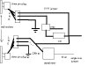
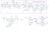
hi, i'm doing a project based on circuits that i will attach. i really need the help to explain how the circuits work especially the power supply part.(Power in and Power out). it's an x10 transmitter using LCD and push button as user interface. also i need help on the modification of the power supply cause it is design for 110V/60Hz. i'm using 240V/50Hz.
thank you.

regards,
fiz
 

Attachments

  • circuits_171.zip
    97.1 KB · Views: 285
You can simply omit one of seial X2 type condenser e.g. C14, and use in VDR position higher voltage type (260....300V). The triac must be TIC206M or N.
 
thank you for your reply.
what if i use a 240V-6V AC transformer like the attached circuit? Is it correct? both C14 and C15 are x2 capacitors but i can't find with the value of 2.25uF. does the difference in frequency60Hz and 50Hz have any effect on the transmission of X10 signal?
Another thing is the pin assignment for LCD display that i bought. The one that i bought has the pin assignment of
1-Vss
2-Vdd
3-Vo
4-RS
5-R/W
6-E
7-14:DB0-DB7
8-9:VLED+ and VLED-

(RS stock no. :184-8538)
in the circuit it is Vcc,Vee, Gnd,Gnd1.
So the question is which pin is the same with the pin given on the circuit.
please advice.
thank you
fiz
 

Attachments

  • transformer_630.jpg
    transformer_630.jpg
    9.3 KB · Views: 1,064
Of course You can use the transformer, but also need the zener or (better) a 78L05 regulator.
The LCD: Vee =Vo, Vss=GND, Vdd=+5V
The varistors connectable in serial.
 
Thanks Sebi.
Can i use BT136 600 for the triac? how to know it is suitable or not? From the datasheet for BT136 600 it is stated that the repetitive peak off-state voltages is 600V max. I can't find the datasheet for TIC206N to make the comparison.
Another thing, the 'Life' connection from power in and power out are connected at some point. So what is the voltage going to the =>x10circuits, 240V or 480V (240V+240V)?
For the LCD pin, what's the function of VLED+ and VLED-? Must i connect them to +5V and Gnd respectively or just leave them unconnected?
thanks

fiza
 
The TIC serie is sensitive gate type, for BT serie need more current to gate with same loading.
No problem with wiring: the live connected to load and neutral connected via triac to load. If the input is 240V, the out is same.
Vled+ and Vled- the backlight LED power. When You need this, need higher power supply (can't supply directly from mains) because suck about 150...200mA. Most of case need external serial resistor also for 5V.
 
thanks Sebi.
I can't find TIC serie so can i still use the BT serie and how can i supply more current to it so that it works like the TIC serie? Or i have to find another sensitive gate triac?
Why there are 2 zener diode in opposing direction in the voltage limiter part?Does it imply=> 6.8V-6.8V=0V. can't i just connect it to ground?
the 2n222 is a switching device right? How does the highpass filter, the 120KHz transmitter and the voltage limitter works/operates?
Do you know/understand about the x10 protocol-sending signal through the power line?
thanks
fiz
 
The BT triac also will work, with reduced serial resistor in gate. I recommend 100ohm. The antiparalel zeners work as AC voltage limiter 7,5V. Don't connect the signal to GND.
PM me with e-mail address, and i send some pdf file what i found on my HDD about X10.
 
thanks

that's great. i don't have to buy another and save my time and budget. thanks Sebi for your recomendation. I'll start the hardware part soon and i'll post the progress of the project. Next i have to built the receiver but later. Thanks again for your help.
regards
fiz
 
If i use veraboard??(brown plate with ready made holes for pins ,not a protoboard) instead of PCB, the jumper wire to connect the power out and in to the other component such as triac and VDR, can i use the usual single core jumper or use a specific jumper that can withstand 240V?
thanks.
fiz
 
The generic jumper useable up to 1..2A just for experiment.
If this circuit not dimmable,i recommend for triac driving an optotriac. For veroboard experiment You can use simply a LED for indicating.
 
actually what i mean is the wire connected to the power line. I'll attach a picture. the bold lines the the one that connect to the power line. if pcb is used, the wire for those lines should be thicker or not? So for jumper(used usually with experiment using protoboard ) that i mean is the thin line. what's your recommendation?
is my sketch the correct interpretation of the circuit??
thanks
fiz
 

Attachments

  • wiring.JPG
    wiring.JPG
    17.2 KB · Views: 951
The PCB track thickness depend from load current. How many amperes (or VA) the load?
 

Attachments

  • wiring_130.jpg
    wiring_130.jpg
    18.7 KB · Views: 913
oh i thought the power out goes to another wall socket. thanks for the input. this may sound stupid to you but i'm not sure what device the load is suppose to be. Is it the x10 receiver or the appliances we want to control? Isn't x10 suppose to enable us to control by remote as long as connected to the same power line?
can you show me how the connection is supposed to be? I'm a bit confused.
thanks.
fiz


Is this the three pin plug (female&male)
 

Attachments

  • female.jpg
    female.jpg
    7.8 KB · Views: 868
  • male_164.jpg
    male_164.jpg
    4.1 KB · Views: 897
  • connection.JPG
    connection.JPG
    6.4 KB · Views: 885
This sematic show one of many receivers with switchable output by triac. You can plug it into any wall socket, and connect a load to output. All receiver have independent address, and with transmitter You can send a command to receivers. So You need a receiver for each load (wall socket)
Unfortunately i never learn english, and can't better explain the exact functions. Try search for X-10 tutorial, i'm sure You can find it.
 
the previous circuits is for the transmitter.
this is the receiver circuit i got from the internet. Can i use D1N4148 for DD1 and also what kind of lamp can i use for #47Lamp?

thanks
fiz
 

Attachments

  • x10Rx1.JPG
    x10Rx1.JPG
    40.3 KB · Views: 448
  • x10Rx2.JPG
    x10Rx2.JPG
    36.6 KB · Views: 439
hi,
i email someone who knows about x10 and he said that the transmitter circuits is actually a tranceiver so it can send and receive the x10 signal. and the power out connection is for whatever load(appliance&lamp) that we want to control.
So if i want to control a light bulb maybe around 60W, can i just connect it directly to the power out?? how i can i do that? can you show me the proper connection?
thanks
fiz
 
one more thing, there is a precaution stated that the x10 transceiver,x10 receiver or the osciloscope must be plugged to an isolation transformer, not directly to the wall socket. why?? and what kind of isolation transformer must i used?
i can't attach the file, too big. the address is
**broken link removed**

thanks
fiz
 
Yes, the 4148 work fine in this position. If Your load only 60W bulb, no need a heatsink for triac, and just connect it to power output.
For experiment quite enough an isolation-transformer about 60...100VA as the application note show. (The circuit suck very low pover just the bulb 60W)
 
Status
Not open for further replies.

Latest threads

New Articles From Microcontroller Tips

Back
Top