Continue to Site

Welcome to our site!

Electro Tech is an online community (with over 170,000 members) who enjoy talking about and building electronic circuits, projects and gadgets. To participate you need to register. Registration is free. Click here to register now.

  • Welcome to our site! Electro Tech is an online community (with over 170,000 members) who enjoy talking about and building electronic circuits, projects and gadgets. To participate you need to register. Registration is free. Click here to register now.

Dont know what protection diode to choose.

Status
Not open for further replies.

rainman1

New Member
I use the below relay driver circuit.
relay-jpg.26522

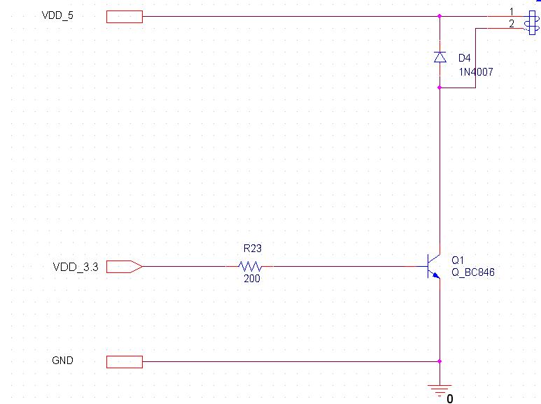
The relay is 5V @ 108mA rated (~46 ohm coil resistance).
I would like to use another protection diode accross the BJT.
What diode should i choose?
What happen if the diode will go into forward state when 5V is applied on it? (when BJT is in cut-off).
Wouldnt the diode cause the relay to have current (5-0.7)/46 to flow through it?
 

Attachments

  • relay.jpg
    relay.jpg
    31.7 KB · Views: 1,132
Well, i would like to add another diode to the transistor.
And would like to understand about it,
I would appreciate if you could answer my questions please.
 
There's no reason to from the circuit you show, but if you insist on adding a protection diode to the transistor then you would add a zener diode from the transistor collector to ground (anode to ground). A regular diode will not work. The zener voltage should be greater than 5V and less than the transistor rated voltage. That way it will only conduct to protect the transistor when there is a transient voltage greater than 5V.
 
Use a switching diode across the coil that can stand the steady state current through the coil.
I don't think the 1N400x series would work in production, but you might get away with it if there is enough parasitic capacitance.
Adding unnecessary components gives you more components to fail and to troubleshoot.
 
Last edited:
Use a switching diode across the coil that can stand the steady state current through the coil.
I don't think the 1N400x series would work in production, but you might get away with it if there is enough parasitic capacitance.
The 1N400x series has a 1A rating so it should be more than sufficient for a 108mA relay.

And I don't see what parasitic capacitance has to do with it. All the diode has to do is conduct the inductive coil current for a short period when the transistor turns off.
 
At least you're not nearly as rude this time. I see you got unbanned.
The diode has to have a fast turn-on time to squelch the transient. If you get away with a slow diode it could be that the coil parasitic capacitance is reducing the risetime or peak value of the transient.
 
Last edited:
The diode has to have a fast turn-on time to squelch the transient. If you get away with a slow diode it could be that the coil parasitic capacitance is reducing the risetime or peak value of the transient.
Yes, the diode needs a fast turn-on time. But it's a misconception that a standard "slow" diode has a slow forward turn-on time. It's true they have a long reverse recovery time to turn-off, but that's not important for a snubber application such as this. The important parameter is the turn-on time and that tends to be fast for just about any diode (See **broken link removed** for measurements of the 1N400X family.)
 
Thanks all.
I dont understand something.
On the one hand, after deactivating, the 108mA coil current will flow through the diode, right?
But on the other hand, the voltage on the diode will be very high, therefore according the IF vs. VF graph (of 1N400x series) the current through the diode should be at least 1A.
So what is right then?
I don't understand why you think the voltage will be high. It will be only what is required for the diode to carry 108mA in the forward direction or about 0.8V.

Look at the current flow direction through the relay when the transistor is on, it's from top to bottom. When the transistor turns off the inductive current now flows from the bottom of the relay through the diode in the forward direction to the top of the relay, in a closed loop, until the inductive energy is dissipated.
 
therefore according the IF vs. VF graph (of 1N400x series) the current through the diode should be at least 1A.
The current thru the diode is max 1A, not minimum 1A.
 
I don't understand why you think the voltage will be high. It will be only what is required for the diode to carry 108mA in the forward direction or about 0.8V.

Look at the current flow direction through the relay when the transistor is on, it's from top to bottom. When the transistor turns off the inductive current now flows from the bottom of the relay through the diode in the forward direction to the top of the relay, in a closed loop, until the inductive energy is dissipated.


T-H-A-N-K Y-O-U V-E-R-Y M-U-C-H-! :)
 
Yes, the diode needs a fast turn-on time. But it's a misconception that a standard "slow" diode has a slow forward turn-on time. It's true they have a long reverse recovery time to turn-off, but that's not important for a snubber application such as this. The important parameter is the turn-on time and that tends to be fast for just about any diode (See **broken link removed** for measurements of the 1N400X family.)
You're good!
:D
 
To make it safe 1000% you might use a TRANSIL diode. They available unidirectional, bidirectional and rated for different voltages.

Boncuk
 

Attachments

  • 1,5KE-15CA.pdf
    76.3 KB · Views: 297
Status
Not open for further replies.

Latest threads

Back
Top