ADWSystems
Member
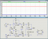
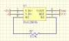
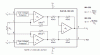
Is the offset applied to the other input multiplied by the gain of the amp or does it pass straight through?
Does the amp work to provide (A) input times gain then add offset, or does it (B) add the offset to the input and then apply gain to the total?
The second question I have is, in non-inverting mode (input to in+) the offset will be applied to in-. To increase the offset on the output, do I apply a positive or negative voltage to in-?
")