Continue to Site

Welcome to our site!

Electro Tech is an online community (with over 170,000 members) who enjoy talking about and building electronic circuits, projects and gadgets. To participate you need to register. Registration is free. Click here to register now.

  • Welcome to our site! Electro Tech is an online community (with over 170,000 members) who enjoy talking about and building electronic circuits, projects and gadgets. To participate you need to register. Registration is free. Click here to register now.

Does this exist?

Status
Not open for further replies.

woodward

New Member
Hi,
Hoping someone here can help me with project I'm working on.

The best way I can describe what I'm looking for is with an analogy.

Example:
A.....fuel or air pressure regulator.

If you have 5 pounds on the supply side, you will have 5 on the delivery side.
10-10
20-20
Regulator is set at 30
30-30
40-30
50-30

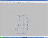
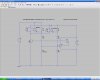
Now, apply this example to resistance.

I need accurate readings from 0 to about 3K but if it goes over that, I need it to be "regulated" at that value. Does anything like this exist?

If anyone can help, it would be greatly appreciated. Oh, please go easy on me, I am a true novice with a limited vocabulary:D

Thanks.
 
As far as I know, this does not exist. You might be able to build one out of common parts though. I'd need to know more about what you're trying to do in order to advise you. Please be as specific as possible in regards to what the input and outputs are.
 
Thank you for the reply.

I made a controller (for lack of a better term) to be placed between an engine sensor and the computer to trick it into believing there is a load when there is not but the sensor is still part of the loop and is functional.

For example, if I place a resistor in line, there will be a false reading that the computer will recognize.

The controller has multiple settings with the resistance increasing as the switch is set to the next setting.

The sensor needs to remain in the circuit and be functional or a problem code will flash but my problem is, if the sensor operates properly and my false resistance is added to sensor reading, the level will go to high and it will throw another problem code. (and the computer will intervene)

I hope this information will help you to help me.
Any other questions, please......ask.

Thank you again.
 
So, are you saying that the added resistor needs to decrease by the same amount that the sensor increases the total circuit resistance when it's operating correctly?

Whar is the resistance range of a properly operating sensor? What are the resistors you are presently using?

Diagrams are always helpful.
 
Last edited:
My hope to find something that would limit the reading beyond a certain resistance value would prevent the computer from throwing up red flags.

I did this from my head to the completed project so i dont have a diagram.

Basically, this is placed between the sensor and the computer, through a 6 position rotary switch which then goes to the circuit board and the various resistors.

The sensor should operate through the unit but depending on the setting, the additional resistance is added.

My guess is the computer will throw up the red flags when a resistance of 4-5K is achieved.

My added resistance values start at 47 and go to 3,400.
If the sensors actual functioning value at a full engine load is say........3,600 then the value of the setting is added, the computer will not be happy.

The sensor operates from 0 (or almost zero) going up in value depending on engine load.

Is my explanation helping or just confusing you and making me look worse? :-/
:)
 
What you want is going to be complicated and difficult to calibrate. The simple solution would be to sense when the sensor is working, and if so, completely bypass the added resistors, and read the sensor only.
 
Yes:

1: Potentiometer emulates the Sensor, with shaft driven by standard RC servo, selecting a 0 to 3 Kohm range.

Rip out servo's electronic PCB, and replace with:

Comparator output driving a H-bridge that drives the servo's motor.

Comparator compares existing Sensor resistance against servo's position feedback potentiometer.
Arrange for the comparator circuit to be self-oscillating, to provide a PWM output for the servo's motor.

Or 2: PIC uC could do a lot of the functionality of the above.

Or 3: Leave the RC servo standard, and make the servo's PWM control signal a function of:
A comparator comparing input Sensor resistance against a sawtooth signal.
 
Last edited:
Easy:

Potentiometer emulates the Sensor, with shaft driven by standard RC servo, selecting a 0 to 3 Kohm range.

Rip out servo's electronic PCB, and replace with:

Comparator output driving a H-bridge that drives the servo's motor.

Comparator compares existing Sensor resistance against servo's position feedback potentiometer.

Arrange for the comparator circuit to be self-oscillating, to provide a PWM output for the servo's motor.

Did you read the part where he said he was a novice?
 
Did you read the part where he said he was a novice?

I did better than that, I read the Title of the OP: "Does this Exist?". Which I think I'd answered quite well, citing 3 examples! :)


I think yours is the most practical solution though.
The simple solution would be to sense when the sensor is working, and if so, completely bypass the added resistors, and read the sensor only.
 
Last edited:
The simple solution would be to sense when the sensor is working, and if so, completely bypass the added resistors, and read the sensor only.

Is that something you would be able explain.........diagram, or???

Let me try this question...

If i limited the controllers resistance to say 3,300, would there be a way to install a circuit that would sense a resistance of say 3,600 or 4K and then bypass the controller allowing the sensors true reading to register and then if the resistance dropped below 3,600 or 4K the controllers resistance would register again?
 
Last edited:

I'll get me one of them there sawtooth resistance comparators, hook it to the PWM servo in series with the RC servo, run that through the uC PIC and allow the self-oscillating resistance comparator to drive my H-bridge potentiometer.

Problem solved!
:D

(Hopefully you have a sense of humor;)
 
Maybe something like this: Transistor Q2 is set to the current to satisfy the computer. R3 represents the sensor, and R2 is chosen to give slightly more than 6V at the "-" input to the comparator. If the sensor is giving > 0 resistance, then the inverting input goes below 6V, and the output of the comparator turns on Q1, which supplies enough current to keep the computer happy.
 

Attachments

  • ResistorRegulator.JPG
    ResistorRegulator.JPG
    74.4 KB · Views: 141
Is that something you would be able explain.........diagram, or???

Let me try this question...

If i limited the controllers resistance to say 3,300, would there be a way to install a circuit that would sense a resistance of say 3,600 or 4K and then bypass the controller allowing the sensors true reading to register and then if the resistance dropped below 3,600 or 4K the controllers resistance would register again?

Yes, that's doable. If you want to do it this way, I can cobble up a diagram.
 
Does this forum have PM's? (private messages)
If its ok with you, can we work on this through email so i can get more info together so you can review it before spending time on a solution?
 
Post the information in the public thread. Although we have PM, we do our work in public.
 
In the attached circuit, the switches and associatd resistors are intended to model realys. If you build this circuit, or a similar one, replace the switches and resistors with relays, and add the protection diode. The sensor is modeled by R1. When the sensor is at zero volts, the relays are de-energized, and the resistance seen by the computer is 3.3kOhm. When the sensor is over 300Ohms, the relays are energized, and the computer is looking at the sensor reisitance plus R1. This version reads an error, becuase it adds the value of R1. We can twittle the values of the reisitors so that error is small, if your system can tolerate that.

Simulation has verified the operation as described.
 

Attachments

  • ResReg2.JPG
    ResReg2.JPG
    95.6 KB · Views: 136
Last edited:
I made a diagram of my contraption. (kindergarten style compared to yours) but i think it will give you an idea of what I'm working with.

The sensor has 3 wires. when disconnected, the wire harness will have 6.5 volts on the brown wire, 5.05 volts on orange and zero on yellow.

When plugged into the sensor, 6.5 brown, 1.something orange, zero yellow.

When i place a resistor in the yellow line, the computer will register the reading.

The system is 12vdc.

After looking at your diagram, I'm still scratching my head :-(
Is there a preschool version available? :)

I don't know how to paste an image with a URL. Can I send it to you and you can paste it so others can see?
(or explain how i can do it?)
 
Last edited:
I don't know how to paste an image with a URL. Can I send it to you and you can paste it so others can see?

Do you just need to link to a webpage that has the image? Just type the URL into the message window, or use the icon above that looks like a chain and globe. Otherwise, sure you can PM it to me, and I'll post it.
 
Last edited:
Is the yellow wire the return? What are the functions of the brown and orange wires?
 
Status
Not open for further replies.

Latest threads

New Articles From Microcontroller Tips

Back
Top