Continue to Site

Welcome to our site!

Electro Tech is an online community (with over 170,000 members) who enjoy talking about and building electronic circuits, projects and gadgets. To participate you need to register. Registration is free. Click here to register now.

  • Welcome to our site! Electro Tech is an online community (with over 170,000 members) who enjoy talking about and building electronic circuits, projects and gadgets. To participate you need to register. Registration is free. Click here to register now.

Does this asm code look correct ? PIC12F509

Status
Not open for further replies.

Darkstar64

New Member
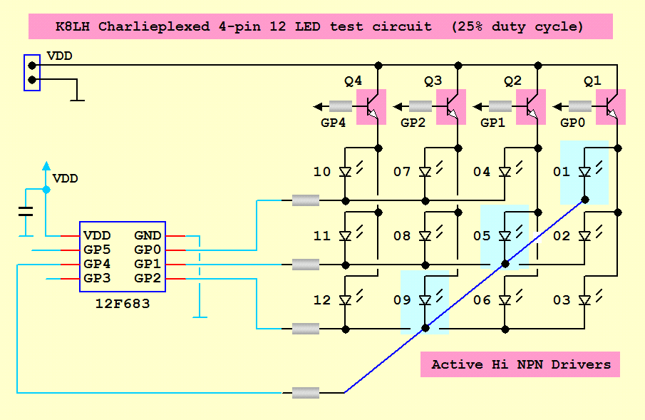
Here is the code im working with im chaliplexing 12 LED's with 4 outputs from the PIC included is the curcuit diagram for refrence. This is for the letter S it should cycle through each LED with a 100 µs delay between LED's as well as it loops 1000 times in 1 second

Code:
Sam
		
		
		clrf	sc			; Sets Counter's loop amount to 256
		clrf	sc1
		clrf	sc2
		clrf	sc3
letS	        movlw	b'000000'	; Clears all LED's to low
		movwf	GPIO
		call	delay100
		movlw	b'010111'	; Letter S Q1 Completly lit
		movwf	GPIO
		call	delay100
		movlw	b'000011'	; Letter S Q2 LED #4 lit
		movwf	GPIO
		call	delay100
		movlw	b'010111'	; Letter S Q3 Completly lit
		movlw	GPIO
		call	delay100
		movlw	b'010111'	; Letter S Q4 Completly lit
		movwf	GPIO
		call	delay100
		decfsz	sc,f		; Inner Loop Counter
		goto	letS
		decfsz	sc1,f		; 1st Middle Loop Counter
		goto	letS
		decfsz	sc2,f
		goto	letS
		decfsz	sc3,f
		goto	letS

Delay Code

Code:
;******************	Delay Subroutine ( 100 µs )

delay100				; Delay W x 100 µs
		movlw	.25		; Delay = ( N x 4 - 1 + 2 cycles = N x 4 + 1 )
		movwf	dc4		; Writes 25 or N to register
dc5		nop				; No Operation
		decfsz	dc4,f	; Decrement Counter
		goto	dc5	    ; If Decrement Counter is 0 then skips this if its not 0 then it loops untill 0
		retlw	0

Diagram everything is based off of this

charlie-12-png.21589
 
You seem to be missing the matrix part of the above display and making things a lot more difficult for yourself than they need be.

If you make GP0 high and GP1, 2 & 4 low then LEDs 1, 2 & 3 will light. This isn't very useful but if we play with the data direction register we can light any combination of these LEDs, if GP1, 2 & 4 are all inputs then no LEDs will light, make one or more of them outputs and the corresponding LED will light. This is how 3 LEDs can be controlled at the same time.

Here's some code which does the multiplexing. With this code each bit in variable LEDs and LEDs2 represents 1 LED. So, you can setup a bit pattern in the variables and call multiplex and the correct LEDs should light. If you change your delay routine to take 250uS then the multiplex subroutine will take 1mS and make for easier timing.

Mike.

Code, untested.
Code:
Multiplex
	movlw	b'11111111'	;make all pins input (all off)
	tris	GPIO
	movlw	b'00000001'	;GP0 high, all others low
	movwf	GPIO
	movlw	b'11111110'	;GP0 output
	btfsc	LEDs,0		;is LED 1 lit
	andlw	b'11101111'	;yes, so make GP4 output
	btfsc	LEDs,1		;is LED 2 lit
	andlw	b'11111101'	;yes, so make GP1 output
	btfsc	LEDs,2		;is LED 3 lit
	andlw	b'11111011'	;yes, so make GP2 output
	tris	GPIO		;move to tris register
	call	Delay		;show the LEDs
	movlw	b'11111111'	;make all pins input (all off)
	tris	GPIO
	movlw	b'00000010'	;GP1 high, all others low
	movwf	GPIO
	movlw	b'11111101'	;GP1 output
	btfsc	LEDs,3		;is LED 4 lit
	andlw	b'11111110'	;yes, so make GP0 output
	btfsc	LEDs,4		;is LED 5 lit
	andlw	b'11101111'	;yes, so make GP4 output
	btfsc	LEDs,5		;is LED 6 lit
	andlw	b'11111011'	;yes, so make GP2 output
	tris	GPIO		;move to tris register
	call	Delay		;show the LEDs
	movlw	b'11111111'	;make all pins input (all off)
	tris	GPIO
	movlw	b'00000100'	;GP2 high, all others low
	movwf	GPIO
	movlw	b'11111011'	;GP2 output
	btfsc	LEDs,6		;is LED 7 lit
	andlw	b'11111110'	;yes, so make GP0 output
	btfsc	LEDs,7		;is LED 8 lit
	andlw	b'11111101'	;yes, so make GP1 output
	btfsc	LEDs2,0		;is LED 9 lit
	andlw	b'11101111'	;yes, so make GP4 output
	tris	GPIO		;move to tris register
	call	Delay		;show the LEDs
	movlw	b'11111111'	;make all pins input (all off)
	tris	GPIO
	movlw	b'00010000'	;GP4 high, all others low
	movwf	GPIO
	movlw	b'11101111'	;GP4 output
	btfsc	LEDs2,1		;is LED 10 lit
	andlw	b'11111110'	;yes, so make GP0 output
	btfsc	LEDs2,2		;is LED 11 lit
	andlw	b'11111101'	;yes, so make GP1 output
	btfsc	LEDs2,3		;is LED 12 lit
	andlw	b'11111011'	;yes, so make GP2 output
	tris	GPIO		;move to tris register
	call	Delay		;show the LEDs
	movlw	b'11111111'	;make all pins input (all off)
	tris	GPIO
	retlw	0
 
O haha I get it now but how would I then call each LED in the Multiplex subroutine I see that it is just configureing the LED's then putting numbers to them so that I can just easly call the the number and not the whole bit and write thing. And then what about the loop do I need it or do I just call the numbers somehow and then add a delay of X then set all the bits to inputs but even then I would have to have it cycle though each colum to refresh the display 1000 times a second so ya im still confused haha also on the build im getting so strange errors here is the log don't wrry about the counter and counter 2 I deleted a few things that casued that just haven't fixed it yet

Code:
Debug build of project `C:\PIC12F509\Programs\LED_Cube_rev2 .disposable_mcp' started.
Preprocessor symbol `__DEBUG' is defined.
Fri Aug 15 10:16:05 2008
----------------------------------------------------------------------
Clean: Deleting intermediary and output files.
Clean: Done.
Executing: "C:\Program Files\Microchip\MPASM Suite\MPASMWIN.exe" /q /p12F509 "LED_Cube_rev2 .ASM" /l"LED_Cube_rev2 .lst" /e"LED_Cube_rev2 .err" /d__DEBUG=1
Error[113]   C:\PIC12F509\PROGRAMS\LED_CUBE_REV2 .ASM 93 : Symbol not previously defined (counter)
Error[113]   C:\PIC12F509\PROGRAMS\LED_CUBE_REV2 .ASM 96 : Symbol not previously defined (counter2)
Message[302] C:\PIC12F509\PROGRAMS\LED_CUBE_REV2 .ASM 116 : Register in operand not in bank 0.  Ensure that bank bits are correct.
Message[302] C:\PIC12F509\PROGRAMS\LED_CUBE_REV2 .ASM 118 : Register in operand not in bank 0.  Ensure that bank bits are correct.
Message[302] C:\PIC12F509\PROGRAMS\LED_CUBE_REV2 .ASM 120 : Register in operand not in bank 0.  Ensure that bank bits are correct.
Message[302] C:\PIC12F509\PROGRAMS\LED_CUBE_REV2 .ASM 129 : Register in operand not in bank 0.  Ensure that bank bits are correct.
Message[302] C:\PIC12F509\PROGRAMS\LED_CUBE_REV2 .ASM 131 : Register in operand not in bank 0.  Ensure that bank bits are correct.
Message[302] C:\PIC12F509\PROGRAMS\LED_CUBE_REV2 .ASM 133 : Register in operand not in bank 0.  Ensure that bank bits are correct.
Message[302] C:\PIC12F509\PROGRAMS\LED_CUBE_REV2 .ASM 142 : Register in operand not in bank 0.  Ensure that bank bits are correct.
Message[302] C:\PIC12F509\PROGRAMS\LED_CUBE_REV2 .ASM 144 : Register in operand not in bank 0.  Ensure that bank bits are correct.
Message[302] C:\PIC12F509\PROGRAMS\LED_CUBE_REV2 .ASM 146 : Register in operand not in bank 0.  Ensure that bank bits are correct.
Message[302] C:\PIC12F509\PROGRAMS\LED_CUBE_REV2 .ASM 155 : Register in operand not in bank 0.  Ensure that bank bits are correct.
Message[302] C:\PIC12F509\PROGRAMS\LED_CUBE_REV2 .ASM 157 : Register in operand not in bank 0.  Ensure that bank bits are correct.
Message[302] C:\PIC12F509\PROGRAMS\LED_CUBE_REV2 .ASM 159 : Register in operand not in bank 0.  Ensure that bank bits are correct.
Halting build on first failure as requested.
----------------------------------------------------------------------
Debug build of project `C:\PIC12F509\Programs\LED_Cube_rev2 .disposable_mcp' failed.
Preprocessor symbol `__DEBUG' is defined.
Fri Aug 15 10:16:06 2008
----------------------------------------------------------------------
BUILD FAILED
 
Last edited:
I would like to help you but you refused to answer my question on your other thread about showing the actual physical LED layout. I just don't see how you can form letters or characters on 12 LEDs and so I don't understand what you're trying to do.

Mike
 
I would have 5 outputs so I could use 16 LED's it would be easyer to make letters out of if that helps I will be using the same multiplex Idea but I need some way to allow me to be able to chose between 2 different things like two different subroutines of different things with one switch like if I hold the switch for 2 seconds it plays one but if I just hit it it plays the other ? and I do prefer 16 LED's over 12 anyday I just had the problem with the switch if that makes sense at all here is the LED pattern im useing I'm only useing a 4 by 4 for 16 LED's so I changed the photo so this is pretty much what im looking at now If I can do the switch thing im talking about that is if not I guess im just going to have to stick with this one I might even have to go with 20 LED's like you have but I wouldn't have a switch so once power is put on it would delay x number of seconds then run But I would like a switch though to control what runs
**broken link removed**
 
Last edited:
Ok guys, help me out here. I'm trying to get the OP to show me how he would physically lay out 12 LEDs to represent a letter. Is there a different way I can ask because he doesn't seem to understand?

Mike
 
haha ok srry I thought you ment layout of the LED's all 12 of them for 16 LED's lets say using the letter A, Colum RB3 LED's A,B need to be lit, Colum RB2 LED's A,D need to be lit, Colum RB1 all LED's need to be lit, Colum RB0 A and D need to be lit is this what you where talking about Mike The layout of all the LED's is a 4x4 sqaure of LED's this is using the diagram above for the LED names its shown above your post Mike thats how its going to be made
 
Last edited:
Ok guys, help me out here. I'm trying to get the OP to show me how he would physically lay out 12 LEDs to represent a letter. Is there a different way I can ask because he doesn't seem to understand?
To do a decent job of it you really need 5x7 (35 LEDs). Maybe he doesn't want to do letters? (haven't read the entire thread)
 
Last edited:
Yes I do want to do letters but the problem is that it will require then 140 LED's something my teacher would say no too since im making a cube haha thats why im starting small just with some simple things the LED's are not going to be touching each other like a normal display there is going to be a few centemters between them so it would look good But letters are not the only thing I'm getting at I just need to know how to write the code I can adapt my curcuit to my needs if I have too I just need to know the code part of it explained better I kinda get the asm code Pommie put up but its not building corretly and I don't know how to call each LED or set what LED's to be on using the bit register ? and there is still the loop problem I'm having so I gave you the layout im using even if I can't do letters I still need to be able to make some good patterns and what not so can we not just concentrate on if the letters will look good or not but helping me to understand how to light each LED then refresh the colums so as to make it look like they are all lighted at the same time but in reality its just cycling each colum for X number of µs then going on the the next for about 2-3 seconds ? and also about the switch part of it is it even possible to do this, If say the button1 is held for 5 seconds a subroutine is called and if its just tapped or held for 1 second then another subroutine is called not the same one though ? I'm srry for not explaining it well I just need to be able to understand whats going on to allow the LED to be on its just the way I learn how to do things. Does this make any sense to anyone ?
 
You only have 2 real errors in that list above. They are the first two because you are using two variables (counter and counter2) that haven't been defined. The other errors (actually warnings) are because you are trying to access the registers above 0x1f. All your variables need to be located at addresses between 0x08 and 0x1f inclusive. This is one of the limitations of using such a simple chip.

Mike.
 
Pommie what do you mean I have moved the code to the start of my program and too the end and the middle but I can't get it to complie can I do something like this to put it in the right spot also I still need to know how to light the LED's what do I do to setup the bit registers and can I do the switch thing I was talking about ? and the refresh thing here is what I have for the switch so far but im still unsure of how to get the Multiplex subroutine in the right spot I tried using the cblock to put it in the right spot
but no luck just a whole bunch of build errors. Here is what I have for the switch I can't write it in asm don't know how to use the if command or even if I can use that so I wrote what I was looking for instead I also have a little bit of code that I worked on don't know if it will work like I want though But I still need help with the bit regiester thing that Pommie was talking about also the refresh and how to configure the bits for the LED rows


test GP3
if GP3 is low then delay 20ms : Debounce
test GP3 once again
if GP3 is low then wait 3 seconds
test GP3 if High then call X2 if low then call X

Code:
loop
waitup  movlw   .2
        call    delay10         ; Delay of 20ms to debounce EITHER switch
        btfsc   GPIO,3          ; Is switch 3 pressed?
        goto    waitup          ;       Yes, wait 20ms and test again
        
test    btfsc	GPIO,3			; Test's if GP3 skip's if high
        goto	test
        movlw	.255
        call	delay10
        btfss	GPIO,3			; If button is still pressed then call's first sub
        call	#1Subroutine
        btfsc	GPIO,3			; If button is not pressed then call second sub
	call    #2Subroutine
		goto 	loop
 
Last edited:
Cblock is used to define variables. Any code should go after an org instruction. If you look in (typically) C:\Program Files\Microchip\MPASM Suite\Template\Code you will find a file called 12F509TEMP.ASM, this file is a template and shows the variables at location 7 onwards and the code after org 0 where it states, "; remaining code goes here". This is where your main code should go and the multiplex routine should go after the main code. LEDs and LEDs2 can be added to the variable list by doing,
Code:
;***** VARIABLE DEFINITIONS
temp	EQU     0x07        ;example variable definition
LEDs	EQU     0x08
LEDs2	EQU     0x09

Mike.
 
Ok it working now I just need to know how to set the bits up and the refresh the only build error is the counter and counter2 variables but I know how to fix that problem so just need help on the other stuff
 
Last edited:
You can't use equates in a cblock section. Just delete the equate part so it reads,
Code:
		cblock	0x07
;***** VARIABLE DEFINITIONS  
dc1,dc2,dc3		; Delay Loop Counters
dc4		; Delay of 100 µs Variable
cv,cv1,cv2,cv3,cv4,cv5		; Loop Counter Variables
LEDs
LEDs2
		endc

You also have subroutines (counter and counter2) that aren't defined.

If I get time I'll have a play with this tomorrow, it's midnight here so a little late to play now.

Mike.
 
Can you try changing your main code to,
Code:
;******** Main Code

start
        movlw   b'001000'       ; Configure only GP3 as a input
        tris    GPIO

loop
waitup  btfsc   GPIO,3          ; Is switch 3 pressed?
        goto    TurnOn          
;turn off LEDs
	clrf	LEDs
	clrf	LEDs2
	goto	Display
TurnOn	movlw	0x55       ;try changing this value
	movwf	LEDs
	movlw	0x05       ;and this one
	movwf	LEDs2
Display
	call	Multiplex
	call	Multiplex
	call	Multiplex
	call	Multiplex

	goto	loop


;****************** Delay Subroutine ( 10 ms )

Mike.
 
Yes this Main code builds fine Pommie here is the log file of it also what about the switch part of it is it possible if you hold the switch down for X number of seconds it will go to one routine but if you just hold it for lets say 1 second it runs a different routine ? I also see how you call the LED's now but im not sure what your getting at about changing the numbers since 0x55 in binary is 01010101 and in decimal its 85 ? and 10101010 doesn't correspond to anything under Multiplex unless you where just showing me how to do it without giving it away in that case I would just need to get the binary changed to Hexadeciaml and thats pretty simple

Code:
----------------------------------------------------------------------
Debug build of project `C:\PIC12F509\Programs\LED_Cube_rev3 .disposable_mcp' started.
Preprocessor symbol `__DEBUG' is defined.
Sat Aug 16 21:04:46 2008
----------------------------------------------------------------------
Clean: Deleting intermediary and output files.
Clean: Done.
Executing: "C:\Program Files\Microchip\MPASM Suite\MPASMWIN.exe" /q /p12F509 "LED_Cube_rev3 .ASM" /l"LED_Cube_rev3 .lst" /e"LED_Cube_rev3 .err" /d__DEBUG=1
Loaded C:\PIC12F509\Programs\LED_Cube_rev3 .cod.
----------------------------------------------------------------------
Debug build of project `C:\PIC12F509\Programs\LED_Cube_rev3 .disposable_mcp' succeeded.
Preprocessor symbol `__DEBUG' is defined.
Sat Aug 16 21:04:47 2008
----------------------------------------------------------------------
BUILD SUCCEEDED
 
What does the code do? What it should do is light half the LEDs when the button is pressed. Changing the two numbers should light different LEDs. If this part is working then to make it change patterns is the next step.

Mike.
 
I can't really test it as I don't have the programmer to do so at the moment its at school and its locked for the summer so all keep this code as a backup can you explain how to get the LED's to light up without just randomly trying numbers and seeing what works and what doesn't ? is it using Hex ? not sure bc 0x55 doesn't correspond to any of the values of the Multiplex routine ?
 
The 12 LEDs are lit by setting a bit in the variables LEDs and LEDs2 (only 4 bits in this one). So, 0x555 should light every odd numbered LED, 0xAAA would light the even LEDs, 0x001 would light just LED1, 0x007 would light LED1,2 & 3 etc.

Without being able to test it on the hardware makes it very difficult to progress. Coding is best done in little steps, get one bit working and then move on to the next.

Mike.
 
Ok well all wait till I get the hardware then but I do still need to know how to do the timed switch if its possible ? allowing 2 different routines to be called depending on how long you hold the switch for
 
Last edited:
Status
Not open for further replies.

Latest threads

Back
Top