Continue to Site

Welcome to our site!

Electro Tech is an online community (with over 170,000 members) who enjoy talking about and building electronic circuits, projects and gadgets. To participate you need to register. Registration is free. Click here to register now.

  • Welcome to our site! Electro Tech is an online community (with over 170,000 members) who enjoy talking about and building electronic circuits, projects and gadgets. To participate you need to register. Registration is free. Click here to register now.

DIY Coil Winder

Status
Not open for further replies.
Hi All
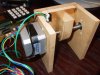
Just to let you know I've not given up on the coil winder just looking at the options and doing some tests.

Main issue is the practicality of using a threaded bar for the traverse system.Before I commit to lots of work especially by other people willing to help out I want to look at it closer.

I'm going to do some test.

Cheers
 
I've had a play with this and got a circuit board built that can drive 2 stepper motors. I'll have a go at getting the hardware built this week and then I may be able to post details.

Sneak peek in attachment.

Mike.
 

Attachments

  • board.jpg
    board.jpg
    61.3 KB · Views: 2,114
Wow, coming along isn't it? Just a matter of time & parts till you have something running. Keep posting as things move along...

Ron
 
Hi all,

Mike was kind enough to leave his schematics to me. I added two extra functions counting the numbers of turns using a Hall-sensor and an emergency-stop button. (The PIC16F877 still had some unused I/O pins :)).

The entire device requires two PCBs, one main board and the count sensor board consisting mainly of a TLE4905 (Hall sensor).

I paid special attention to keep the board single sided with straight wire jumps. The sensor board is also single sided (top layer only). Note that the south pole of the magnet must face the sensor for proper turns count.

If Mike takes care of the software you should have good tool to wind all kinds of coils (as long as the stepper motors can handle the coils).

Here are some pdf files for the project.

Everybody interested in the Eagle files might PM me leaving his email address. Eagle files were generated using Eagle version 3.55 professional, but can be handled by any newer version, not trying to move any part on the PCB because of the board size limitation of the light version (100X80mm). Possible error messages about "restring" can be ignored.

Main board size is 173.99X99.3775mm (6.8375X2.9125inches)

Regards

Boncuk
 

Attachments

  • COILWINDER-1-SCH.pdf
    90.5 KB · Views: 1,448
  • COILWINDER-1A.pdf
    13 KB · Views: 1,086
  • COILWINDER-1-BRD.pdf
    308.7 KB · Views: 1,090
  • COILWINDER-1-SOL.pdf
    255.5 KB · Views: 1,045
  • COILWINDER-1-TOP.pdf
    37.9 KB · Views: 1,017
  • COILWINDER-1-SILK.pdf
    64.3 KB · Views: 905
Last edited:
I've not forgotten about this. I built a carriage (attached) but it binded quite badly due to it not being straight. I've half built a second one and should get time to finish it next week.

Thanks Hans for uploading the board etc. If anyone is planing on making their own I did a single sided version with bigger clearances. I'll post the solder side if anyone is interested. I didn't bother with the hall sensor as I planned on keeping track of the number of steps. The attached image of the board shows a 16*2 LCD but it fits a 20*4 as shown on the assembled board.

Mike.
 

Attachments

  • carriage.jpg
    carriage.jpg
    110 KB · Views: 1,150
  • carriage2.jpg
    carriage2.jpg
    69.5 KB · Views: 973
  • board.png
    board.png
    30.6 KB · Views: 2,256
  • Assembled.jpg
    Assembled.jpg
    103.5 KB · Views: 1,452
Thanks Mike and Hans.
Hi

Thanks Boncuk and Mike for the extensive effort.

I am very interested in making my own coil winder from the info supplied.Is final build still using one stepper for coil winder and one for wire traverse?

I'm not at the level of making my own PCB. although I ought to be giving it a go!! so might end up using vero board.
I will follow Han's schematic for that.!!!!

Boncuk did you add extra code so You could use an Hall effect counter?
Is the final code ready to share?

I am so pleased with this thread and to those who help out others.

Kind regards
Mark
 
Hi Mark,

unfortunately I have not the slightest idea how to write code for a µC. :(

I just try to do good circuit and PCB design. :)

Mike would certainly not have introduced the project if weren't ready to share the code with everybody interested in the circuit.

I guess one of the reasons why the device didn't wind as desired is certainly the fact, that he uses a worm gear without the necessary precision.

Thinking of coils with 0.06mm copper diameter (1,300 turns on a bobbin of 8X10X4mm (outer diameter height and inner diameter)) I had to wind (manually) once the slip in the worm gear will mess up the overall result pretty well. Not wound accurately the final coil exceeds the outer diameter which should slip into a cylinder.

I guess using a deflection coil instead of a stepper motor and a worm gear will have better results with almost no mechanical restriction.

If I get the time I'll travel to Bangkok and have a look for precision worm gears to be used for accurate turn by turn windings.

Regards

Boncuk
 
I managed to have a play with this today and a few problems have appeared. The 16f887 is not big enough and I have severely run out of stack space - solution, ordered some 18F4620. I will run out of room with the free BoostC compiler very soon - solution, going to switch to the C18 compiler.

For anyone curious, this is what it does so far,

And the code so far is attached. It's a bit rough and I had to move the step code inline to keep within the stack limits, hence the very long interrupt. I should be able to tidy it up when the new chips arrive.

Mike.
 

Attachments

  • CoilWinder.c
    5.9 KB · Views: 1,000
Last edited by a moderator:
Hi Mike
Great work thus far!!:)

Did you include traverse limits set up 'left/right' so the length of coil can be adjusted, far beyond me to workout the coil winding speed to the traverse speed and put in to auto mode:eek: I suppose if you have independent control both can be married up..

What are you going to use for turn counting?
Boncuk is using Hall effect sensing, does your code allow for this as a readout on the LCD.?

I'm very excited by this but I will wait until you have a working model before I go in feet first.

Will I be ok to make up the board at this stage? don't want to get ahead of myself!!

Kind regards
 
Hi Mark,

At the moment you can set the limits via the keypad. For the traverse speed I envisage entering the wire diameter and it calculating the speed internally. For counting the number of turns I'll simply keep track of the steps the motors have done, 200 steps = 1 rev. You could make up a board at this stage but it's probably worth waiting a while as invariable something will need refining. If you are going to have a go at making it yourself I can post an image of the board. I just noticed an error on Hans board so don't use that one yet.

Hans,
I just noticed on your schematic that Mclr isn't connected to the ICSP socket (A3 is instead).

Mike.

Oops! Will be corrected right away.
 
Hi Mike,

MCLR was connected correctly to the ICSP-connector. There were just two adjacent nets making it look like the connection was made to RA3.

However I forgot use a pull up resistor for MCLR. It's added now (R15, 10K)

If you count the motor steps without feedback you actually don't know if the motor has moved with every step.

A Hall-sensor to count actual revolutions won't hurt.

Regards

Hans
 

Attachments

  • COILWINDER-1-SCH.pdf
    90.8 KB · Views: 900
  • COILWINDER-1-BRD.pdf
    311.3 KB · Views: 843
Last edited:
improved PCB design

Hi All,

I changed the schematic applying some "cosmetic" corrections. Now it should look clear.

All power traces have been increased to a width of 0.056" (1.4224mm) and the rest is 0.016" (0.4064mm).

Via diameter and drill are 0.056" (1.4224mm) and 0.032" (0.828mm)

The PIC18F4620 is pin compatible with the PIC16F877. All I changed there was the device "value".

Boncuk
 

Attachments

  • COILWINDER-1-SCH.pdf
    95.7 KB · Views: 824
  • HALL-SENSOR-SCH.pdf
    13.8 KB · Views: 638
  • COILWINDER-1-BRD.pdf
    88.4 KB · Views: 680
  • COILWINDER-1-SOL.pdf
    45.3 KB · Views: 748
  • COILWINDER-1-TOP.pdf
    37.3 KB · Views: 606
  • COILWINDER-1-FILL.pdf
    266.1 KB · Views: 716
  • COILWINDER-1-SILK.pdf
    64.5 KB · Views: 655
Precise traverse drive

Hi again,

the only precise way to wind a coil is using a ball screw with (almost) zero lag.

The wire feed must stop 1/2 wire width at both ends of the bobbin and reverse direction.

Have a look at this data sheet.

Boncuk
 

Attachments

  • NookMetricBallScrew.pdf
    1.1 MB · Views: 1,162
Last edited:
How to couple a stepper to ball screws?

the only precise way to wind a coil is using a ball screw with (almost) zero lag.

Hola Boncuk,

What is a pratical and reliable way of coupling a stepper to a ball screw?

And what if I want to ensure the possibility of changing the initial stepper for a bigger/smaller one (thus bigger/smaller shaft). Any "universal" (non expensive) solution possible?
 
Coupling and mechanical details.

For anyone curious, this is what it does so far,

Hola Pommie,

Understand that this is still an ongoing project.

How did you manage to couple the stepper to the worm? Are you using bushes or bearings?

From the video I cannot say how you did it. More details you give, the better. Mechanics is not my strongest point.

I will appreciate any information you can give.
 
Hello :

I´m Carlos from Portugal and it´s the first time i use forum, well i need to transform the code C++ in ASM to put inside pic.
What is the program to make that operation ?
I´s it possible to you put here the code in ASM or Hex?


Thanks for your help!
Sorry bad english!


Carlos Pires
 
Status
Not open for further replies.

Latest threads

New Articles From Microcontroller Tips

Back
Top