Continue to Site

Welcome to our site!

Electro Tech is an online community (with over 170,000 members) who enjoy talking about and building electronic circuits, projects and gadgets. To participate you need to register. Registration is free. Click here to register now.

  • Welcome to our site! Electro Tech is an online community (with over 170,000 members) who enjoy talking about and building electronic circuits, projects and gadgets. To participate you need to register. Registration is free. Click here to register now.

DIY bluetooth speaker

Status
Not open for further replies.
Well if you look at the last battery, its connected directly to + of the DC source. So basicly, it can never stop the charging of that battery, the way i see it. What am i seeing wrong ?
 
The protection board has 6 contacts for sensing the individual battery cells but two of them are wrongly not connected.
The protection board is cheap, Chinese and might not have connection instructions in English so we are just guessing.
Try it like this:
 

Attachments

  • protection board.png
    protection board.png
    73.4 KB · Views: 212
I already ordered another bms, because to be honest i don't want to playtest this bms with strange connections when fire is in play. I ordered this BMS:

$_3.PNG

I also ordered two extra things for safety, since i dont trust this BMS much. I ordered a 6A fuse, i will use 2 or 3 in series because well, i dont trust the fuses either, its all from ebay. And then i ordered a NC thermal fuse. I will connect it to batteries and as soon as temperature will reach 60 or more, it will disconect the batteries from everything else. Do i need to mention i will use 2 of this fuses in series aswell ? So what are your thoughts on this project so far ?
 
You need to find out the minimum power supply voltage needed for the BMS to supply 21V plus the voltage drops across all your fuses.
You also need to find out if the maximum charging and discharging currents for the BMS will explode your lithium battery.

But you still will not have a proper Lithium battery charger circuit that detects low battery current then tries to charge at a low current and shuts off if the voltage goes not increase normally and detects a full charge then shuts off to avoid damaging trickle charging.

Why do you risk a fire or explosion from buying cheap no-name-brand ebay junk?
 
I am not sure i am following. Would that mean that as soon as 1 battery is over 4.2V, charging will stop for all of them ?

Read the numbers off the chips, and download the datasheets for them, they will explain what they do. As far as I'm aware they bypass the current once a cell is charged, not remove it.
 
The reason i am buying things from ebay is that i am on a budget.
Genuine electronic parts are inexpensive and can be bought locally from a reputable distibutor. The parts work properly.
Cheap parts bought from a "seller" on ebay are no-name-brand and might be defective, might be designed wrong or use fake parts. You are gambling because they might not work then you probably must replace them. Cheap no-name-brand parts bought on ebay might cause a fire or explosion. Then you are throwing away your time and money.
 
Genuine electronic parts are inexpensive and can be bought locally from a reputable distibutor. The parts work properly.

So where are you going to find inexpensive battery protection boards from a local reputable supplier?, even assuming you can find someone who has them, they will be buying them from the same Chinese source as the EBay sellers.
 
The Li-PO batteries in electric radio controlled model airplanes do not have protection boards. They are charged with a multi-wires balanced charger and the electronics in the model limits the maximum discharge current and cuts off the high current motor when the total voltage drops to 3.2V per battery cell but leaves the low current radio receiver and servos operating so the model can be controlled while gliding in for a landing.

A few of us in this thread asked the thread starter, "why are you using a cheap protection board instead of a proper charger"?
One cheap protection board claimed limiting the charging current to 56A!
 
The Li-PO batteries in electric radio controlled model airplanes do not have protection boards. They are charged with a multi-wires balanced charger and the electronics in the model limits the maximum discharge current and cuts off the high current motor when the total voltage drops to 3.2V per battery cell but leaves the low current radio receiver and servos operating so the model can be controlled while gliding in for a landing.

All of which as nothing whatsoever to do with this thread, as we're not discussing model aircraft. But it explains your weird charging and protection arrangement.
 
Like i said, beside BMS, i will add temperature and current fuse. But yes, i understand the problem. I am wondering, overcharge (voltage over 4.2V). Why does the battery explode ? Does it heat up or not during that charge to high voltage, for instance 4.5V.
 
Like i said, beside BMS, i will add temperature and current fuse. But yes, i understand the problem. I am wondering, overcharge (voltage over 4.2V). Why does the battery explode ? Does it heat up or not during that charge to high voltage, for instance 4.5V.

Lithium is a highly reactive metal, and burns easily.

The protection board, along with the correct 21V charger, will do everything you need - temperature monitoring is only really required if you're attempting to charge the batteries very fast, in which case you need to monitor their temperature, and drop the current if they get too hot. I originally build LM35's in my battery packs, but as I wasn't fast charging them I never used them, so have stopped fitting them now.

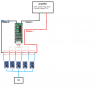
The protection board provides over current protection, making a fuse not required, although it's never a bad idea to add one. I use one on the DC input for the charger circuit (as it charges from a 12V car battery).

Charging Li-Ion is pretty easy, you need a constant voltage source (21V in your case) that does current limiting - these are easily and cheaply available as modules from China. Set the voltage to 21V, the current to what you want, and connect to the battery - this is all included in the ready made mains charger you looked at.The charger will supply the constant current to the battery, and the voltage will rise as it charges, once it gets to 21V the charger will switch to constant voltage, and the battery is fully charged. The protection pack on the battery takes care of any other issues, and will probably disconnect the charge slightly before it's 100% charged, for safety reasons.
 
Could you tell me why this setup wouldnt work ? Individualy charging each cell, that way charger takes care of overcharging. I could make a switch between batteries -> amp and batteries -> charger. This would be very cheap since those little chargers cost like 70 cents a piece. And obviously, i would never use charger when the amp is turned on, it can either be charged, or play, but never both at the same time.
 

Attachments

  • version 2.png
    version 2.png
    239.4 KB · Views: 195
You would need 5 entire separate, and completely isolated 5V supplies - with no common connections at all (particularly earth), or nasty things will happen. It would be a very complicated way to charge it. These little charger boards also have a degree of battery protection, they switch the output off when the battery gets too low.

That diagram still shows two of the protection board wires not connected, so wouldn't work properly anyway.
 
Forget about bms wires, i ordered different bms altogether. Could you tell me why 5V power suply has to be seperated for each board and why cells cannot be in series when i charge them individualy ? It seems there are no simple solutions ..
 
Forget about bms wires, i ordered different bms altogether. Could you tell me why 5V power suply has to be seperated for each board and why cells cannot be in series when i charge them individualy ? It seems there are no simple solutions ..

Because the chargers aren't isolated - the negative 5V input on the USB socket (or the two PCB pads) is connected directly to the negative output to the battery. So if you power them from the same supply you're putting adirect short from the negative of one battery to the negative of the next (with is also the positive of the first one) - BOOMMMM!!!!!.

There are simple solutions (the correct one), I've already given one to you - a proper 21V charger and a protection board, such as you already had, but wired correctly.
 
Ok, i ordered a liion 21V charger, it says its liion, i hope its not a normal 21V power suply. And i ordered a proper bms, proper meaning cheap but at least i am sure what to wire where. I will let you know how it protects cells during charge, i hope none of them will go beyond 4.3 (4.2 would be perfect but i doubt it)
 
I can't say I've ever had any urge to check how well the protection boards work?, and it would be hard to check the call balancing, as long as the cells are new and from the same batch they should charge pretty level anyway. Mixing old and new cells would be more of a problem.
 
Status
Not open for further replies.

Latest threads

New Articles From Microcontroller Tips

Back
Top