diy didi
Member
Hi
I have been woking on a bench power supply for the past two months or so.
I decided on a discrete regulator design with adjustable voltage and and current limit.
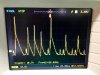
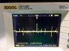
Yesterday I boxed most of it, and decided to test using a couple of parallel connected 12V car bulbs. The bulbs were flickering slightly. Scoped the output and revealed a 16- 25HZ almost square wave/ round edges type oscillation or motor boating.
If i turn down the current limiting it gets even worse.
With my DC load all works as it should.
My electronics knowledge doesn't stretch as far as to fix this. The sense leads come together at the croc clips of the output leads. So there are four wires coming out of the box. The negative output terminal connects directly to neg of main filter caps.
Connecting a 4700uF capacitor across the leads at the load doesn't help much.
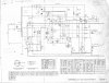
Any ideas? See schematic attached.
I have been woking on a bench power supply for the past two months or so.
I decided on a discrete regulator design with adjustable voltage and and current limit.
Yesterday I boxed most of it, and decided to test using a couple of parallel connected 12V car bulbs. The bulbs were flickering slightly. Scoped the output and revealed a 16- 25HZ almost square wave/ round edges type oscillation or motor boating.
If i turn down the current limiting it gets even worse.
With my DC load all works as it should.
My electronics knowledge doesn't stretch as far as to fix this. The sense leads come together at the croc clips of the output leads. So there are four wires coming out of the box. The negative output terminal connects directly to neg of main filter caps.
Connecting a 4700uF capacitor across the leads at the load doesn't help much.
Any ideas? See schematic attached.