Hi all
EDIT: I cannot change the topic title.. negative voltages are not a problem as I redesigned the way I'd connect this project.
I have a few spare Arduino boards ( they allow to make stuff happen by feeding analog or digital inputs) can control relays and other cool stuff..
I have a hobby solar setup with about 24v 400AH setup as (2x 12v 400AH banks) each bank has 4 batteries.. for a total of 8 batteries..
There seems to sometimes be one bank with more voltage then the other.
Instead of spending about $40-50 on a balancer. I want to make one. I like the idea I can change the discharge load. Where the brought one would be at best only a small load. Maybe undersized for 400Ah
So my Arduino can take the voltages from the banks and decide who has the highest voltage and discharge it via a relay with a load until eaual. I can add delays and timers to the code in Arduino ensuring it doesn't run all day etc.
So id want to connect the 24v and 12v as inputs and convert them to around the 5v range.
So my last question, input on Arduino needs to be 5v maximum.. having 12/24v from the battery would always read as 5v. I need to divide the input or do something.
Eg, divide the voltage by 3 or 6.
Arduino 5v = 15v battery
Arduino 2.5v = 7.5v on the battery
And other input
Arduino 5v = 30v
This would be difficult because I'd want a higher accuracy in the 8v to 15v range
Essentially wishing
Arduino 0v = 8v battery
Arduino 5v = 15v battery
Other input
Arduino 0v = 16v battery
Arduino 5v = 30v battery
I hope that makes sense.
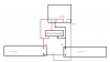
Please see my diagram for a rough idea of how I would want to connect it.
Last of all I have a box of capacitors different sizes and a box of resistors with almost all valesv. If possible can this be done only using resistors and capacitors.. no transisors! As I don't have them and would complicate the circuit.
Cheers.
Shaun
EDIT: I cannot change the topic title.. negative voltages are not a problem as I redesigned the way I'd connect this project.
I have a few spare Arduino boards ( they allow to make stuff happen by feeding analog or digital inputs) can control relays and other cool stuff..
I have a hobby solar setup with about 24v 400AH setup as (2x 12v 400AH banks) each bank has 4 batteries.. for a total of 8 batteries..
There seems to sometimes be one bank with more voltage then the other.
Instead of spending about $40-50 on a balancer. I want to make one. I like the idea I can change the discharge load. Where the brought one would be at best only a small load. Maybe undersized for 400Ah
So my Arduino can take the voltages from the banks and decide who has the highest voltage and discharge it via a relay with a load until eaual. I can add delays and timers to the code in Arduino ensuring it doesn't run all day etc.
So id want to connect the 24v and 12v as inputs and convert them to around the 5v range.
So my last question, input on Arduino needs to be 5v maximum.. having 12/24v from the battery would always read as 5v. I need to divide the input or do something.
Eg, divide the voltage by 3 or 6.
Arduino 5v = 15v battery
Arduino 2.5v = 7.5v on the battery
And other input
Arduino 5v = 30v
This would be difficult because I'd want a higher accuracy in the 8v to 15v range
Essentially wishing
Arduino 0v = 8v battery
Arduino 5v = 15v battery
Other input
Arduino 0v = 16v battery
Arduino 5v = 30v battery
I hope that makes sense.
Please see my diagram for a rough idea of how I would want to connect it.
Last of all I have a box of capacitors different sizes and a box of resistors with almost all valesv. If possible can this be done only using resistors and capacitors.. no transisors! As I don't have them and would complicate the circuit.
Cheers.
Shaun
Attachments
Last edited:
