Continue to Site

Welcome to our site!

Electro Tech is an online community (with over 170,000 members) who enjoy talking about and building electronic circuits, projects and gadgets. To participate you need to register. Registration is free. Click here to register now.

  • Welcome to our site! Electro Tech is an online community (with over 170,000 members) who enjoy talking about and building electronic circuits, projects and gadgets. To participate you need to register. Registration is free. Click here to register now.

Distance measurement project

Status
Not open for further replies.

bigfarmerdave

New Member
Ok, I am a bit new to this so I'll ask you guys to take it a bit easy on the first timer. My goal is to build a circuit that measures the distance from point A to point B. Point A being the end of an arm that is suspended over the ground and point B being the ground itself. Total distance between the two points could range from 6 inches to 6 feet. Anyway, as the arm travels over uneven ground, the distance between the arm and the ground changes and I would like to eliminate those changes by maintaining a set distance. So as I travel across the ground, I want to capture that (distance) data whether it be measured in voltage, frequency... and compare it against a set value and change the height of the arm over the ground accordingly so that the arm always maintains a specific distance above the ground. What I am lacking is a way to measure the distance. Any devices or ideas out there that anyone would recommend?
Thanks,
Dave
 
A capacative pick, or is there farm machinery to be considered. One solution I have recently found is an audio FM chirp sonar http://nerdipedia.com/tiki-index.php?page=Sonar+CE&PHPSESSID=d56850b944a6fb8c2b668fdbef5b3f6e, it may only be suitable for static applications. The most obvious is a ultrasonic rangefinder or tapemeasure,. Does the arm come in contact with the ground, via wheel? If it does it would be possible to connect a variable resistor at the axis and produce a voltage dependent on the angle of the arm and therefore hieght.
 
Yes, you are correct in your hunch, there is farm machinery involved. In fact it is a sprayer boom that I would like to suspend above the ground a specific distance from the ground while traveling across rolling terrain. I had thought about an ultrasonic approach. Sometimes the arm does get close enough to the ground that the wheel on the end of the boom does make contact with the ground. For that reason, I put a micro switch out there that is activated when the wheel touches the ground and it automatically raises the boom at that point. Problem is now I have to manually (well I guess just pushin the lever) lower it back down to the height that I want.
 
Hi BF Dave,

Some more details would probably help:

1) At what speed will the arm be required to travel over the ground?

2) No matter what solution you choose there will be *some* lag after the time the arm arrives over a given spot on the ground before the system can respond and get the arm adjusted. How much lag is acceptable?

3) Like super_voip, my first thought was "ultrasonic rangefinder". I know it's relatively simple to build and program one, since I did it and got it working and I'm not exactly audioguru ;). Also, you can buy quite good ultrasonic rangefinder sensors from SparkFun for around USD $25:
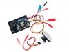
 https://www.sparkfun.com/commerce/product_info.php?products_id=639

4) What kinds of surfaces will the thing need to be able to work over? Must it work over pavement? Gravel? Short grass? Tall grass? Some surfaces will have a tendency to reflect or absorb whatever it is you try to bounce off them (sound waves, IR, etc) to different degrees, so you'll need to set a limit on what you expect it to cope with.

5) What amount of error in the height maintenance are you willing to accept? Is it good enough if the arm maintains its height to within 1 cm of what you set? How about 10 cm? Or does it need to try to stay within, say, 1 mm of its set height?

There are a bunch of other more detail-oriented questions but those are some general ones I'd try to answer before starting to buy components for a project like that. (For instance, what kind of power supply is available; what size/weight constraints are there; do you already have the arm and height adjustment stuff built and just need the sensor or do you still have to design the height adjustment hardware; can you use microcontrollers or must it be discrete electronics; etc).


Torben
 
One thought - to use a laser/optical system.

Imagine looking straight down at the ground from 6 ft or so thru a tube - so you only see a small spot. Then imagine that from another point - possibly a few feet away (horizontally) a laser is pointed at the spot - a sensor could see that, especially if it were pulsed so one could differentiate between that and other light sources. You'd know the laser is at an angle and with some triginometry you could calculate the height. That's great for a static system.

To make it suitable for moving - you'd pivot the light in a plane that would always put the light within the field of view of the tube regardless of elevation (within the limits of your needs). You might then pivot the laser thru the range comparing the angle at any moment to the light sensor. When the sensor see light you can calculate the elevation at that moment. You'd want to do this rapidly and then condition the output somewhat to account for minute changes in elevation that might not matter to you.

Not a wonderful way but it's a way.
 
I'll have another try, the real problem is that the ground is undulating and the boom needs to "see" the ground before it, not below or after it. The tractor is towing the boom? or is the boom attached to the tractor. Now this is closer to robotics, but if a 3 axis sensors was mounted on the tractor, it would "sense" if the boom was about to come close to ground eg if the tractor tilted left it would probably mean the ground on the right was rising.
One other approach, video, probably wouldn't help as the foliage makes it hard to get a good ground reference.
 
Lots of good questions and ideas by all. First I will answer some of your questions. The arm, or more specifically the sprayer boom, is mounted behind a pull type cart. The tractor used to pull the cart usually travels between 5-12mph while spraying. Acceptable lag time to respond to changes in the grounds contour is unknown at this point. I guess the ultimate goal is to keep the ends of the sprayer booms from ever coming into contact with the ground. The sprayer will be used across a variety of surfaces including dirt, dead composting crop residue from previous year, soybeans, medium/short (under 12") grasses, three foot tall corn. I see where your concerns are as far as different surfaces. There shouldn't be any reason to run it on gravel or pavement. Acceptable error in height management is not near as critical as you mentioned. If we can maintain our desired height to with 6"-12" would probably be acceptable. Closer tolerances would be better but I could handle 6"-12" accuracy either up or down from desired height.

The laser idea is interesting but looks like it would involve far more math and processing knowledge than I have.

I've seen the 3 axis sensors and was wondering if they might serve as sort of a second sense for this thing. Rather than waiting for the ultrasonic range finder to sense a sudden or violent change in terrain, the 3 axis sensor might pick that sudden dip up faster than the ultrasonic range finder.

As far as controlling the height of the boom, the way I currently do it is I have an electric over hydraulic valve block and simply toggle an single pole double throw switch back and forth so the mechanics is done, just have to figure out how to automate it now.
 
Perhaps you could try this horizon sensor that is used for model airplanes. You could mount one on the end of each boom. $50 each. See: **broken link removed**
 

Attachments

  • futm0999.jpg
    futm0999.jpg
    17 KB · Views: 200
The only problem with the 2/3 axis idea is that the ground the booms are over may not be the same as the tractor but I'm going to assume the booms are to be used in fields rather than beside tracks, in which case the coupling between the tractor and towed boom might also act as a positional guide.
The tractor end would provide the predictive section.
Once you have decided upon the approach the electronics could probably be handled by a couple of comparators and a bit of logic. Or if you are hady, most farmers are, just add some microswitches to a sensing "yoke" probably only need heavy gauge fencing wire for that. As I see it if the yoke attached to the tractor passes a point, determined by the wire, then the micro is activated and the boom is raised. You can figure how to lower it.:)
 
Last edited:
Did you say how long the booms were. Some crop sprayer can have quite a span.

The trailer wheels keep the booms near the wheels at the right height. The measurment needs to be done at or near the boom tips.

The only thing you should be looking at is the boom to ground distance. A axis sensor will not provide useful info. On a side hill the entire rig will be tilted but there is no need to raise or lower booms.

I would look to see what the OEMs of spray equipment are doing. Could be they have already put the effort into finding what will work. Duplicate or buy their solution.

Also check for patents.

This one

I am not sure how powerful the ultrasonic tranducers need to be.

The operation of the cylinders for raising and lowering the boom assemblies is controlled by a height control system which utilizes ultrasonic signals for determining heights of the boom assemblies above a field or crop surface
 
My next door neighbor was spraying his rye grass field yesterday. He uses a large tricycle sprayer with four foot tall soft field tires and two 40 foot booms. On the end of each boom is a vertical nylon tube that appears to measure clearance from the ground.

Mechanical measurement, like a hanging tube seems to be a more simple and effective method than sonar sensing. It should work over bare ground and short grass type fields. It gets more complex over corn stubble. But with the proper stiffness to the tube even wheat stubble might not be a problem.
 
You are correct in your thinking, the ground that the ends of the booms are over is not the same ground that the tractor is driving over. Each boom, originating from the center of the sprayer, extends 45 feet out from the sprayer for a total spraying width of 90 feet. The tractor tires are on 5 foot centers and the sprayer tires are on 10 foot centers so they don't even follow the same wheel track. Thus, having a sensor on the tractor to predict what is coming may give false readings because they are in different wheel tracks than the sprayer. The sprayer is a pull type cart on which the boom is mounted. The sprayer boom has also got an accumulator on it (giant shock absorber) so that the boom doesn't mirror every single variation across the terrain. "Once you have decided upon the approach the electronics could probably be handled by a couple of comparators and a bit of logic." <-That is exactly what I was thinking! I've been thinking about your idea of a yoke..... there may be some options there.... need to brainstorm on that one some more. On my dirve home last night I was thinking about the 3 axis sensor and side hills. If your on a side hill, the sensor would recognize that and make what changes? As stated above, it is very likely that you could be on a side hill and the boom need no adjusting what so ever because they are still the correct distance above the ground, just that the angle of your ground plane has changed. Thanks for the ideas guys, I'm going to keep on this. Any new thoughts or ideas are muchly appreciated. There are systems out there that are to do what I want to accomplish but I've heard mixed results about them and the cost is of them is plenty. Probably looking at better than $9,000 for a kit and you might still be the guineapig for the company.
 
If the tractor tilted reletive to the boom that would add a predicitive element but with the ends of the boom 45' away from the tractor it probably is that helpful. BTW the control yoke would have to be directly above the pivot point, a spring mounted piece of PVC conduit mounted verticaly on the boom side passing thru the centre, think of a big joystick mounted upside down.
Maybe real (not doppler, sorry Doppler)radar could help here.
**broken link removed**
this is an automotive radar module for cruise control, maybe something like this.
 
Last edited:
Hi bigfarmerdave,

One simple but not perfect way would be to hang something like a length (or a very narrow "V"-shape) of lightweight plastic pipe from near the end of each boom. The pieces would be able to rotate freely from front-to-back, but not side-to-side. They might be clamped into their rotating parts so that their heights above the ground could be adjusted initially, depending on crop conditions, etc. A switch (or you could possibly use a potentiometer or rotary encoder if you needed to get fancier) would be activated whenever the bottom of the piece of plastic pipe (or whatever) was pulled backward by contact with something below, by a certain (probably small) angular displacement, which would tell the system to raise the boom. When the pipe or whatever was no longer contacting anything below, and fell back to being vertical, the switch would open and the boom would stop rising.

That would enable maintaining a (rough) minimum clearance, but would not lower the booms if they ended up too high. Actually, if nothing else were done, it would almost guarantee that they'd end up too high, eventually, since they would follow upward contours but not downward ones. So, for "rigid, hanging ground-contact sensors" in general, it seems like you'd either a) have to have the rest of the system constantly try to lower the booms, to "feel for the ground" with the sensors, or, b) have them always be in contact with the ground and have two switches, to keep them within some preset range of "drag angle", so that the boom would raise if the angle of the sensor got too shallow and the boom would lower if the angle got too steep.

Also, you'd probably have to experiment with the weight of the hanging "sensors", to avoid crop damage. And it would probably be nice to find a way for their whole assembly to be pushed very easily from side to side by a row-width or so, so they might be able to "automatically" slide into the middles of rows of things like 3 foot tall corn, so that they and the corn wouldn't bother each other as much. You might be able to attach a "V" shape (or something) to them, near the ground, to help guide them. (Or go crazy and put video cameras and motors on them so you could guide them from side to side.)

You'd probably want an easy way to disengage the sensors' switch system, for manual control, and for when starting at the ends of the rows (until they got centered between rows, for example), and would probably also want to make sure that the system couldn't lower the booms unless you were moving, etc etc. And you'd want to make sure to have over-riding limit switches for the total height-adjustment limits, if you don't already have them.

- Tom Gootee

**broken link removed**
 
Status
Not open for further replies.

Latest threads

New Articles From Microcontroller Tips

Back
Top