Continue to Site

Welcome to our site!

Electro Tech is an online community (with over 170,000 members) who enjoy talking about and building electronic circuits, projects and gadgets. To participate you need to register. Registration is free. Click here to register now.

  • Welcome to our site! Electro Tech is an online community (with over 170,000 members) who enjoy talking about and building electronic circuits, projects and gadgets. To participate you need to register. Registration is free. Click here to register now.

Dissecting an absolute encoder

Status
Not open for further replies.

Kal_B

Member
Hello,

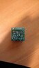
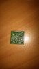
I've been curious about this encoder I found in garage door openers and how it encodes a position. I gathered a bunch of pictures some I took myself some off the internet.
This is what we have:
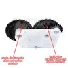
-Three through beam photo eyes U1-U2-U3 place
-Two wheels:
- Wheel# 1: Has two discs, outside disc with regularly sized and spaced notches and a second disc with irregular sized and spaced teeth.
-Wheel#2: Has one disc with irregular sized and spaced teeth

The connector pin-out is: GND, +5V, 64, 63, CLK

How does it work, as in how does it determines a position based on those three eyes?

Thanks
 

Attachments

  • IMG_20190917_204110.jpg
    IMG_20190917_204110.jpg
    1.2 MB · Views: 196
  • IMG_20190917_204220.jpg
    IMG_20190917_204220.jpg
    1.4 MB · Views: 186
  • IMG_20190917_204244.jpg
    IMG_20190917_204244.jpg
    1.5 MB · Views: 187
  • IMG_20190917_204317.jpg
    IMG_20190917_204317.jpg
    1.1 MB · Views: 197
  • wheel view 1.jpg
    wheel view 1.jpg
    77.3 KB · Views: 183
  • wheel view 2.jpg
    wheel view 2.jpg
    72.9 KB · Views: 178
  • wheel view 3.jpg
    wheel view 3.jpg
    38.6 KB · Views: 186
Alright I think I got the general idea after a bit more research. It must be using Gray code most likely using the two irregualry discs and the regular disc would be the clock which may also be used for positioning along with the Gray code. It will be fun to code something for it.
 
I'll be interested if you find out how this works. One thing about Gray coding is that only one bit at a time changes so there's no need for a clock.

Mike.
Edit, do the two wheels have differing numbers of teeth?
 
And yet another thought, is really an absolute encoder or like they really call it a travel module since the number of turns will need memory to hold the number of turns.
 
I'll be interested if you find out how this works. One thing about Gray coding is that only one bit at a time changes so there's no need for a clock.

Mike.

I intend to soder together an interface to connect it to a PLC to play with it (of course I will come here for help). The clock is for speed measurement which is used for safety so that it senses obstruction or if the door is heavy and I'm now guessing counts the turns as part of a semi-multi-turn absolute encoder.
 
It must be using Gray code
I am not completely convinced.
I am also not convinced that this can be described as an "absolute" encoder.

There are only three data bits, generated by the three slotted opto switches.
With three bits, there can only be 8 discrete states.
When the system is switched on from cold, I do not see how it would be possible to determine the absolute position to better than one of eight possible positions.

All this is just my semi-inspired guess, I am prepared to be proved wrong.

JimB
 
Unfortunate it looks like I burned one of the eyes as it is never on; the other two worked fine but without all three it was not possible to tell what was going on. I will buy another one next by the need of the week.
As per attached images the patterns on the discs are different and quite possibly have to be placed in a specific orientation to generate a usable code.
I am thinking the one marked clock, which is the regularly slotted/space ouside disc, has multi function; speed measurement, a clock for data read, sort of like how SSI protocol works and part of three bit pseudo -gray code.
As JimB stated it could not be absolute encoder because it has no memory circuitry to keep track of its position. It must be the circuit board (processor) that keeps track of the position using the clock signal in part as a multi-turn wheel to count how many time the 8bit sequence repeated. Of course that means that if the encoder gears turned while the power is off then it would have the wrong position when the power is turned on. I will also test that, in time, on a live opener.
 

Attachments

  • IMG_20200701_201153.jpg
    IMG_20200701_201153.jpg
    1.1 MB · Views: 182
  • IMG_20200701_201133.jpg
    IMG_20200701_201133.jpg
    1.1 MB · Views: 178
Last edited:
It may be using a distance-coded system?

With the irregular spacings of the slots, it may be possible to determine the position within a small amount of travel by monitoring how many clocks wide the bars & gaps from each other sensor are.
 
One thing that I do not see are timing marks on the wheels which would make it easy to align the wheels together during assembly. Similar to the timing marks which are found on the crankshaft and camshaft pulleys in an internal combustion engine, which allow the thing to be assembled with the correct valve timing.

If you want to try and work out the coding of your wheels, you could do this:

AA Timing Wheel 2.png


Take a picture of the wheels, preferably from vertically above the wheel.
Using an editor program, I used MS Paint, draw radial lines from the centre of the wheel to the edges of the clock pulse "pillars".
Then look at where the code pillars intersect the radial lines, and see if there is a 0 or a 1.
In my fragment above, going from left to right (clockwise) we have

0, 0, 0, 0, 1, 0, 1, 0, 1, 0, 0, 1, 1, 1, etc

not forgetting of course, that by the time the data gets into the electronics, the bit sense may be inverted, ie 1s become 0s and 0s become 1s.

Have fun! :)

JimB
 
Hi Kal_B. as has covered is grey code, but there are several other coding schemes also depending on the designer.
Wiki has a good blog about these encoders with drawings, GIF animation and truth tables.
Applications include robotics, positioning equipment, even fancy telescopes.
I might suggest the wheel with even interrupters is for speed feedback control, the other wheel for positioning.
Myself, have a ghost project with an incremental encoder, like used in large printers, wheelchair, electric bikes etc.
Over the decades, have lost all my simple circuits so have to come up with one myself. A/B quadrature, an up/down pin and 14 bit counter to control a DDS generator.
I may just code a PIC cpu for the task adding the complexity and speed issues
Read through the wiki, that will help you understand what you are looking at.
I am also guessing your door controller has a brain and servo drive doing the work.
 
Status
Not open for further replies.

Latest threads

New Articles From Microcontroller Tips

Back
Top