Continue to Site

Welcome to our site!

Electro Tech is an online community (with over 170,000 members) who enjoy talking about and building electronic circuits, projects and gadgets. To participate you need to register. Registration is free. Click here to register now.

  • Welcome to our site! Electro Tech is an online community (with over 170,000 members) who enjoy talking about and building electronic circuits, projects and gadgets. To participate you need to register. Registration is free. Click here to register now.

Dimplex DH212 Dehumidifier - Compressor Not Starting

Status
Not open for further replies.

mcquaim

Member
Hi Folks,

Another day, another issue...

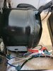
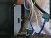
My mother-in-law has the above Dehumidifier for the last 4-5 years and it's been working away fine until two days ago.

The fan is still kicking in but the compressor isn't starting and resulting in no water being collected.

I saw some posts online about dehumidifier compressors not starting and it was usually the result of a capacitor dying and simply needed replacing.

I opened this unit expecting to find a large cylinder capacitor but none was to be found.

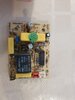
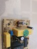
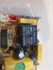
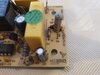
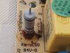
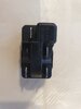
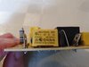
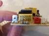
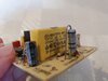
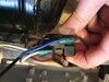
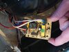
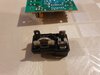
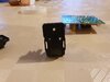
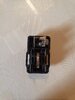
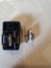
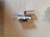
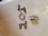
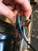
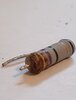
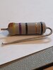
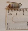
All that really is inside electronically wise is the attached two components. Well, these are located down near the compressor, one is actually plugged into the side of the compressor.

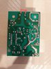
On the small circuit board, one little component, sparks a bit when the fan it kicking in when it starts up, it's brown and burnt looking in the circuit board photo. Is this a resistor?

If this was faulty would it prevent the compressor motor from starting up?

Anything else to check on this board or that other black plug?

Thanks,
Mac
 

Attachments

  • 20201107_111326.jpg
    20201107_111326.jpg
    1.5 MB · Views: 316
  • 20201107_111334.jpg
    20201107_111334.jpg
    1.3 MB · Views: 325
  • 20201107_111352.jpg
    20201107_111352.jpg
    1.4 MB · Views: 353
  • 20201107_111406.jpg
    20201107_111406.jpg
    3.1 MB · Views: 205
  • 20201107_112114.jpg
    20201107_112114.jpg
    1.2 MB · Views: 288
  • 20201107_112847.jpg
    20201107_112847.jpg
    435.1 KB · Views: 281
  • 20201107_110713.jpg
    20201107_110713.jpg
    844 KB · Views: 517
The three yellow rectangular blocks are capacitors. Post photos of the labels on those components.
The big black block is a relay.
The resistor with the corrosion is a possible issue.
 
The three yellow rectangular blocks are capacitors. Post photos of the labels on those components.
The big black block is a relay.
The resistor with the corrosion is a possible issue.
Hi there,

Thanks for the quick reply and for the details.

I've attached photos of the 3 of those capacitors, the one behind the burnt resistor is hard to get a good angle for a photo.

Hopefully you can make out what it is though...
 

Attachments

  • 20201107_135847.jpg
    20201107_135847.jpg
    3.1 MB · Views: 238
  • 20201107_135902.jpg
    20201107_135902.jpg
    2.9 MB · Views: 200
  • 20201107_135915.jpg
    20201107_135915.jpg
    2.7 MB · Views: 226
And, do you have a volt meter?
Please post a photo of the bottom of the board.
 
I don't think it is the resistor itself . It has some form of glue on the bottom, and that discolored possibly due to heat from the resistor itself. The resistor does not look overheated. Any sparking could be a cold solder joint at that resistor (and producing excess heat on the glue). One would have to look at the traces on the bottom of the board.
Common failure is a bad relay, "burned out" so to speak. The rest of the control board seems to be ok, no obvious burned out components. The yellow caps seem to be more along the line of AC filter caps or noise suppressors than anything else. The yellow cap nearest the "COMP" power pin is too low to be a motor start capacitor (0.068uF). It is probably to suppress voltage spikes from the relay.
I once took apart a dehumidifier, and the compressor did not have any external motor start capacitor.
What is the "black plug"? It could be a motor start contactor. The big bump in the upper right could have an embedded motor capacitor, though it seems a bit small to me. Those motor start contactor/relay can "die" as well.
Thus. my primary suspicion is the "black plug", followed second by the relay on the board as the most likely points of failure. That all said, if there is open sparking around that resistor, a cold solder joint could prevent AC power from properly getting to the rest of the circuit. Find out what is sparking first, pinpoint it.
 
And, do you have a volt meter?
Please post a photo of the bottom of the board.
Hi there,

Yes, I've a wee meter alright. What would you like me to test?

I am not just home at the minute so I will take a photo when I get home in an hour or so
 
I don't think it is the resistor itself . It has some form of glue on the bottom, and that discolored possibly due to heat from the resistor itself. The resistor does not look overheated. Any sparking could be a cold solder joint at that resistor (and producing excess heat on the glue). One would have to look at the traces on the bottom of the board.
Common failure is a bad relay, "burned out" so to speak. The rest of the control board seems to be ok, no obvious burned out components. The yellow caps seem to be more along the line of AC filter caps or noise suppressors than anything else. The yellow cap nearest the "COMP" power pin is too low to be a motor start capacitor (0.068uF). It is probably to suppress voltage spikes from the relay.
I once took apart a dehumidifier, and the compressor did not have any external motor start capacitor.
What is the "black plug"? It could be a motor start contactor. The big bump in the upper right could have an embedded motor capacitor, though it seems a bit small to me. Those motor start contactor/relay can "die" as well.
Thus. my primary suspicion is the "black plug", followed second by the relay on the board as the most likely points of failure. That all said, if there is open sparking around that resistor, a cold solder joint could prevent AC power from properly getting to the rest of the circuit. Find out what is sparking first, pinpoint it.
Thanks for the reply.

I will post the photo when I get back later but it looks to me to be making a decent connection from the underside anyway.

That little black plug plugs into the side of the compressor unit. It can open but not much in it, a flat disc looking thing between the contacts... Not sure what it is.

The sparks from that resistor are quite large, it's what is scorching the glue... I just presumed when they were that big it must be blown...

Anyway, I will post a few more photos in a while.
 

Attachments

  • 20201107_110519.jpg
    20201107_110519.jpg
    1.3 MB · Views: 233
  • 20201107_110820.jpg
    20201107_110820.jpg
    1.6 MB · Views: 222
  • 20201107_152337.jpg
    20201107_152337.jpg
    518.3 KB · Views: 203
Here is the underside of the board and I also opened that little plug that connects to the compressor unit to show what's inside.

I marked two red lines to show the connection for the resistor for reference.
 

Attachments

  • 20201107_161738.jpg
    20201107_161738.jpg
    2.6 MB · Views: 210
  • 20201107_162054.jpg
    20201107_162054.jpg
    3.2 MB · Views: 216
  • 20201107_162105.jpg
    20201107_162105.jpg
    3 MB · Views: 219
The black box is a Klixon relay of some sort, something that is used to pass higher energy (power) to the motor. It is possible the relay is shot, or whatever is driving it is failing. As for the resistor, hard to tell for sure, but I would still re-solder the pins of it on the underside of the board. There could still be a cold solder joint that "looks ok", but has intermittent connection. The resistor seems to be a 47 ohm resistor, probably a 2W or 3W metal film type of resistor, hard to determine the size of it from the photos. If possible, remove it and measure the resistance of it. If close to 47 ohms, it is not the resistor. That said, no harm replacing it anyway, just in case there is some internal damage that only shows up under load (cracked resistor).
 
Yes, I would reflow the solder on the resistor (heat with soldering iron to let the solder wick up the lead and make a good bond.
I am now guessing that the relay has welded the contacts together so the compressor never turns off.
 
Yes, I would reflow the solder on the resistor (heat with soldering iron to let the solder wick up the lead and make a good bond.

I will give that a go in the morning...

am now guessing that the relay has welded the contacts together so the compressor never turns off.

Do you mean never turns on? It never starts currently... I can open that black box (picture attached above) but it's a very basic looking device!!
 
The black box is a Klixon relay of some sort, something that is used to pass higher energy (power) to the motor. It is possible the relay is shot, or whatever is driving it is failing.

The pictures attached above show the inside of the black Klaxon relay. It's a very mechanical looking device. How can I test this or know if it's failed?
 
Picture of the Klixon does not show the insides very well. See if you can find the armature of the relay and move it back and forth. If it does not move, some contacts may be fused together.
 
I think it could be a PTC thermistor starter. I have seen this method used before. A picture looking down into the device would be more help.
This is a link to thermistor type motor starters.

Have you traced the wiring between the control board and the motor and checked that the motor is being supplied with power. This would be the first logical step to decide if the fault was on the control board or the motor / start winding control.

Les.
 
Last edited:
I think it could be a PTC thermistor starter. I have seen this method used before. A picture looking down into the device would be more help.
This is a link to thermistor type motor starters.

Have you traced the wiring between the control board and the motor and checked that the motor is being supplied with power. This would be the first logical step to decide if the fault was on the control board or the motor / start winding control.

Les.
Hi Les,

Thanks for the reply.

I have attached some more pictures of the relay from the top and from the internal components.

The top pin appears to be the component that opens/closes the circuit. From testing that top pin using the multimeter it appears to be creating a constant connection. Perhaps when power is sent to this relay it breaks the circuit?

I haven't tested that the power is getting to the relay but it would have been the best starting point alright... When I saw that resistor sparking initially I just presumed that I already had my fault, I guess it still could be.

I am going to reset that now shortly and then I will connect it back to the dehumidifier and test what voltage is getting to the relay.

Thanks again,
Mac
 

Attachments

  • 20201108_093506.jpg
    20201108_093506.jpg
    1.5 MB · Views: 199
  • 20201108_093531.jpg
    20201108_093531.jpg
    1.6 MB · Views: 157
  • 20201108_093554.jpg
    20201108_093554.jpg
    1.5 MB · Views: 174
  • 20201108_093625.jpg
    20201108_093625.jpg
    2 MB · Views: 176
  • 20201108_093812.jpg
    20201108_093812.jpg
    1 MB · Views: 165
  • 20201107_110519.jpg
    20201107_110519.jpg
    1.3 MB · Views: 205
Hi folks,

So, I removed my resistor to test it but it looks to be blown. The shell around the bottom is burst looking. I have attached a few photos.

I tested it with the multimeter also but it's not giving a reading apart from 1. If I touch the two multimeter pins together it's reading 0.00 so no contact is being between the two ends of the resistor by the looks of it.

I was trying to work out what the resistance value was for this resistor by looking up the colour coded chart but I appear to have an extra line on this resistor?

So, yellow, violet, black, gold, black

47 X 1 = 47 with tolerance of 5%

What is the black line at the end mean?

Can anyone point me in the direction for what I need to purchase?

Thanks,
Mac
 

Attachments

  • 20201108_104625.jpg
    20201108_104625.jpg
    199 KB · Views: 170
  • 20201108_104715.jpg
    20201108_104715.jpg
    323.4 KB · Views: 187
  • 20201108_113012.jpg
    20201108_113012.jpg
    454.5 KB · Views: 183
Last edited:
Hi folks,

So, I removed my resistor to test it but it looks to be blown. The shell around the bottom is burst looking. I have attached a few photos.

It doesn't 'look blown', the discolouration at the bottom is from the glue that was securing it in place.

The final black band could be temperature coefficient?.

But assuming it is 47 ohm, and it reads O/C - then it's obviously faulty. Have you any idea what it does?, or why it might have failed?, mostly a resistor is caused by something else.

Hi Nigel,

Thanks for the reply.

It's hard to make out from the first photo but they grey casing at the bottom of the resistor is cracked/burst but the burning/discoloration is hiding it a bit.

In regards to what it does, I'm a complete novice so I wouldn't know.

I will try and trace the board and see where is going to afterwards or coming from before the resistor.

Cheers,
Mac
 
I think it could be a PTC thermistor starter. I have seen this method used before. A picture looking down into the device would be more help.
This is a link to thermistor type motor starters.

Have you traced the wiring between the control board and the motor and checked that the motor is being supplied with power. This would be the first logical step to decide if the fault was on the control board or the motor / start winding control.

Les.

the Datasheet for the MSC series of relays from Klixon are exactly as you suggest - PTC devices. You can read "MSC" on the OP's photo. About a $15 part.


1F4FADA3-E3E8-4C28-948C-D9F38347F31D.jpeg
 
Looking at the traces, the 47 ohm resistor seems to be in series with the AC feed to the controller circuit, but not the feed to the Klixon device. That seems to be handled by the realy. In other words, it seems to feed power to the controller board. The purpose may be to limit any surge current on power up.
Your resistance reading of "1", is that the same reading with the leads open? If so, then yes, that resistor may be at fault. Based on the body length of about 16mm, it looks like a 3W carbon film resistor. Any metal film or carbon film 3W resistor will do as a replacement. One key thing is to get a proper replacement (same color codes).
 
Status
Not open for further replies.

Latest threads

New Articles From Microcontroller Tips

Back
Top