vne147
Member
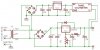
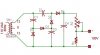
Hello everyone. I have a question that I would appreciate your help with. I built a variable voltage power supply a while ago using an LM317. I am just getting around to putting it into an enclosure that will have a digital voltmeter mounted on the outside so that I can quickly see what voltage is being output. The voltmeter I bought when I initially started the project says that it requires an independent 9V power supply. What I think that means is that the 9V for the voltmeter and the measured voltage cannot have the same ground. I attached a schematic of how I plan to do this. The ground for the LM317 portion of the circuit is simply the "-" pole of the bridge rectifier B1 while the ground for the 9V is connected to the 3rd prong of the AC outlet. The voltmeter I will be using in the PM-129A (link to datasheet below). So here are my questions:
1. Is my assumption in this statement, "What I think that means is that the 9V for the voltmeter and the measured voltage cannot have the same ground.", correct?
2. Will the method I am using in the schematic to seperate the ground paths work?
3. Other than using a 9V battery, is there an easier way to acheive an indepent power source for the digital voltmeter other than how I have shown it in the schematic?
4. This question is not related to the design but to information in the datasheet. This voltmeter is supposed to measure 0 - 500 V DC but on the datasheet under the specifications section the maximum input is listed as 199.9 mV DC. How can the voltmeter measure up to 500 V DC if I can't apply anymore than 199.9 mV DC to it? I think I'm misinterpreting the datasheet but can some explain to me what the 199.9 mV DC limit applies to?
Thanks in advance for your help.
Voltmeter datasheet:
https://www.electro-tech-online.com/custompdfs/2008/11/PM-129ABspecs.pdf
Schematic:
Attachments
Last edited:
")

