Continue to Site

Welcome to our site!

Electro Tech is an online community (with over 170,000 members) who enjoy talking about and building electronic circuits, projects and gadgets. To participate you need to register. Registration is free. Click here to register now.

  • Welcome to our site! Electro Tech is an online community (with over 170,000 members) who enjoy talking about and building electronic circuits, projects and gadgets. To participate you need to register. Registration is free. Click here to register now.

Digital temperature sensor

Status
Not open for further replies.

Philo3_6

New Member
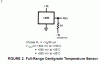
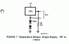
Hey I'm trying to build a digital temperature sensor with a lm35 in the ranges -15'C to 45'C. The lm35 has ranges from -55'C to 150'C and is 10mV/C.
I'm connecting the sensor to a CA3162 and a CA3161 then to 3 LED displays. The CA3162 has a input range of -99mV to 999mV, while the lm35 has an output of -550mV to 1500mV.

I want to use a 5 volt supply and not with a +-5V supply.( on the lm35 datasheet theres a figure to use single supply. How do i connect the sensor to the lm35 ? do i need to use tension dividers or do i connect it directly to the to HI & LO of CA3162? and do i need to put a bypass filter on the sensor?

THis is for a school project, the sensor actually has to be on a remote distance? are there any recommendations on the isolation of the sensor.

A completely different topic is: if i would want to transfer my signal wireless to a receiver that then displays the temperatuur, how do i do that and what products do i need?
 
Last edited:
The CA3162 will only go to -99mV so you would have to use a 10:1 voltage divider (two resistors of 18kΩ and 2kΩ) at its input if you wanted a direct readout in degrees C (-15mV to +45mV), thus you would only have a two digit readout. Is that acceptable?

If so, you should be able to connect the CA3162 input through the 10:1 divider, to Vo as shown in Figure 7 in the LM35 data sheet.
 
@crutschow

Well those were my intensions to have the voltage divider 10:1, But i was being puzzled if i still have to set a low pass filter or any kind of filter on the input? i dont mind two digit output as long as i get '-' when its negative.

@fsmyth
Do i need a buffer? and why? I'm still a student so i'm trying to understand everything really clear. I mean i do know what a buffer does, i just want to know its function in the circuit here and where do i put it? inbetween the sensor and the voltage divider? or do i use the op-amamp to do the 10:1?

And do i transmit it wirelessly if i wanted to??
 
Last edited:
hi philo,
Using the double diode and 18K circuit shown in the datasheet for the LM35 you get -55 thru 150degC.

Its possible to use one diode and a 9K[ two 18K in ||] to give a range of
-27.5 thru +150degC.

The outputs are the same as the two diode version, that is from the LM35 output pin and the LM35 pin that goes to the diode.

What length is the 'long' cable going to be.?:)
 
Last edited:
hey thanks,

The cable isn't going to be that long maybe 1to2 feet. We have to build with the thought that the sensor would be remote and the display will be somewhere else getting the reading. But we decided to use a cable instead of wireless transmission because we haven't got that topic yet @ school. But it would have been gr8t to do have it.

And about bring the range to -27'C to 150'C is it necessary? Because here in the netherlands the temp doesnt reach below the -15'C lets say so we choose those values, but if the sensor reads untill -55'C i wouldnt mine as long as my range(-15'C to 45'C) is displayed.

hi,
A wire length of upto 1mtr will not be a problem with a LM35,
I would just twist the two signal wires together in order to reduce any pick up.

Using the two diode version will be OK over the limited range of -15C thru +45C.
As you know thats a 'change' of 60Cdeg at 10mV/C ie: 600mV

What supply voltage are you using for the LM35
 
Last edited:
the supply voltage will be 5 volt..

& do you know any good program to make schematics and PCB boards..
I'm using Multisim and Ultiboard from National Instruments but they dont have all the components in order to make this schematic and PCB board
 
the supply voltage will be 5 volt..

& do you know any good program to make schematics and PCB boards..
I'm using Multisim and Ultiboard from National Instruments but they dont have all the components in order to make this schematic and PCB board

hi,
I understand Eagle is quite a good program, look here for info.
 
Using the double diode and 18K circuit shown in the datasheet for the LM35 you get -55 thru 150degC.

Its possible to use one diode and a 9K[ two 18K in ||] to give a range of
-27.5 thru +150degC.

The outputs are the same as the two diode version, that is from the LM35 output pin and the LM35 pin that goes to the diode.
How do you make those calculations? i would like to learn based on what?

And thanks for the link for eagle:)
 
How do you make those calculations? i would like to learn based on what?

And thanks for the link for eagle:)

hi,
Do you have the datasheet for the LM35.?

Look at this extract from the data:
Look at the current/resistor values for the two diode version and adjust the values to suit one diode.

Another free pcb program is expresspcb it has a schematic and pcb layout program. Google for it.
You can make your own symbols as required.
 

Attachments

  • esp01 Oct. 03.gif
    esp01 Oct. 03.gif
    7.8 KB · Views: 670
  • esp02 Oct. 03.gif
    esp02 Oct. 03.gif
    5.1 KB · Views: 567
Last edited:
hi,
Do you have the datasheet for the LM35.?

Look at this extract from the data:
Look at the current/resistor values for the two diode version and adjust the values to suit one diode.

Another free pcb program is expresspcb it has a schematic and pcb layout program. Google for it.
You can make your own symbols as required.

YEs i have seen it in the datasheet. Well to me according to your calcualtions, the range would stay the same from -55C to 150C just with one diode. How did u get the -27.5C?
 
Status
Not open for further replies.

New Articles From Microcontroller Tips

Back
Top